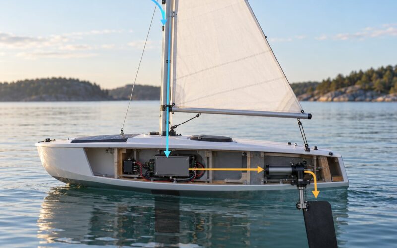
How servo rudders work on autonomous boats is really a question about one chain: a heading sensor feeds a controller, the controller sends a pulse-width signal to a geared servo, the servo horn moves a linkage, and the rudder generates a side force that yaws the hull. The loop repeats several times a second, comparing where the boat actually points against where it was told to point.
That is the whole trick. A servo rudder is not special because the servo is clever. It is special because it turns a steering command into a physical angle quickly and repeatably, and because the controller keeps correcting until the boat’s heading matches the order.
If you are building an unmanned surface vessel, this guide walks the chain end to end, then covers the parts that decide whether it survives salt water and a field test.
Table of Contents
- What Is a Servo Rudder on an Autonomous Boat?
- How the Steering Signal Reaches the Rudder
- How Servo Rudders Work on Autonomous Boats
- How a Servo Creates Rudder Torque
- Why Rudder Placement Matters
- How to Choose a Servo for Marine Use
- Waterproofing, Wiring, and Mechanical Protection
- Feedback, Sensors, and Failsafe Behavior
- How to Test a Servo Rudder Safely
- Common Servo Rudder Problems
- Frequently Asked Questions
- Start With a Safe, Measurable Steering Test
What Is a Servo Rudder on an Autonomous Boat?
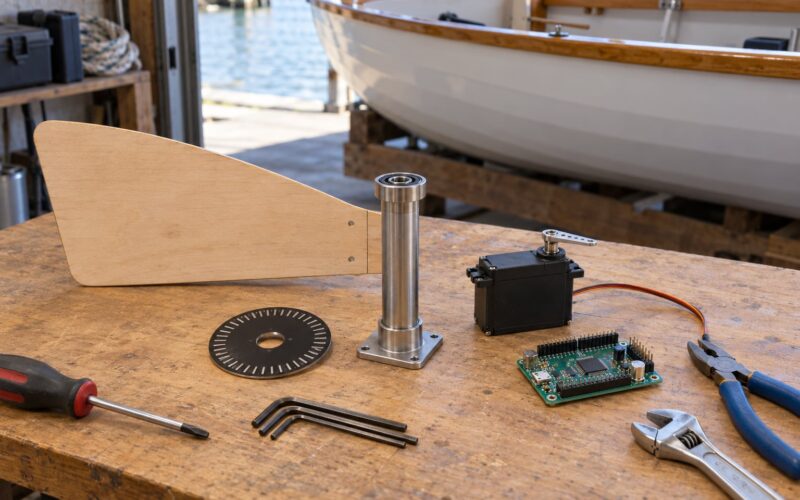
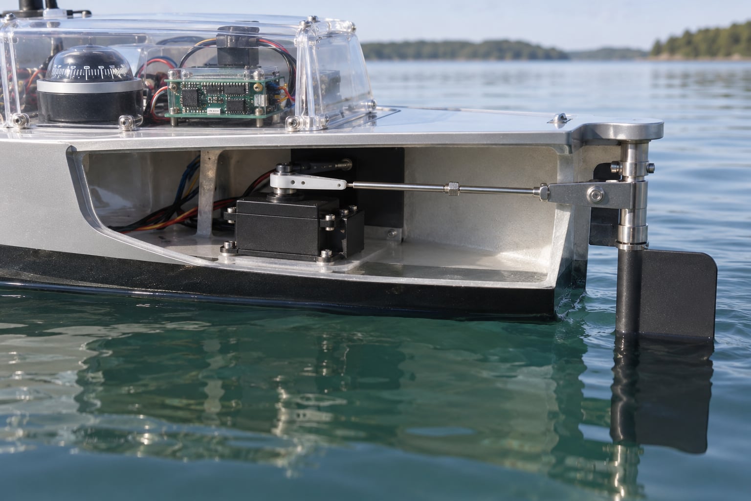
A servo rudder is a complete steering assembly, not just a motor. It has five working parts: the servo, the servo horn, the steering linkage, the rudder stock, and the rudder blade, plus whatever electronics issue the command to the servo.
The servo is a DC motor with a gearbox, a position sensor inside the gearbox output, and a small control board. It holds a commanded angular position as long as it has power and as long as the load stays under what the gearbox can deliver. The horn is the lever arm bolted to that output shaft. The linkage transfers that motion across the boat to the rudder stock, which is the vertical shaft the blade sits on.
It is worth separating that from the alternatives. A fixed or vending-style rudder has no actuator at all; it only works usefully on a boat going forward at speed, and a small autonomous boat often is not. Hydraulic steering uses a pump and a ram, which scales to a commercial vessel but is heavy and leaks. An outboard’s own steering is mechanical, driven off the tiller or the steering servo inside the cowl, which means the steering function disappears if the engine fails. A dedicated servo rudder keeps working with the propulsion system off, which is exactly what an autonomous boat wants during a mission.
How the Steering Signal Reaches the Rudder
Trace it from the front of the boat backwards. Each stage has a defined input and output, and each one has its own way of failing quietly.
| Stage | Input | Output | What goes wrong |
|---|---|---|---|
| Heading sensor | Earth field, GPS satellites, inertial rates | Heading in degrees, 0 to 360 | Motor current deflects the reading by up to 10 degrees; heel tilts an untilt-compensated compass |
| Autopilot controller | Heading plus commanded heading | Error term, then a rudder demand | Heading wraparound bug sends a 355-to-5 correction the wrong way around the circle |
| PID stage | Error, integral history, error rate | A single number for rudder demand | Gains too high hunt forever; loop updating too slowly, the rudder lags the correction |
| Servo driver | Rudder demand | Repeating pulses, roughly 1000 to 2000 microseconds | Voltage sag on the servo rail browns out the servo mid-turn |
| Servo and horn | Pulse train | Angular position at the horn | Buzzing or stalling under sustained load; gear backlash and linkage slop |
| Linkage and stock | Horn rotation | Rudder blade angle | Rod slips in its clevis and leaves the rudder hard over |
| Hull | Rudder angle plus forward speed | Yaw moment and a new heading | Too little speed, or past the stall angle, and the rudder does almost nothing |
Two details in that table decide most projects. The heading sensor is upstream of everything, so a compromised magnetometer corrupts the whole loop no matter how good the rudder is. And the servo is usually fed from a separate regulator rather than the propulsion bus, because motor current is exactly what ruins a cheap compass.
How Servo Rudders Work on Autonomous Boats
The autopilot compares measured heading to commanded heading, subtracts one from the other to get a heading error, runs that error through a PID controller, and converts the result into a pulse width sent to the servo.
Standard hobby servos read a repeating pulse train on one signal wire, typically at 50 Hz. Pulse width sets the target angle: around 1000 microseconds is one end of travel, around 1500 is centre, around 2000 is the other end. Because the signal is a repeating stream rather than a steady voltage, a servo that loses its signal entirely stops receiving valid pulses and behaves according to its own failsafe setting, which on many units is to drive to centre and stop.
Here is the part people miss: the servo compares its own output position against the commanded position internally, continuously. A potentiometer or encoder on the gearbox output tells the servo’s own electronics where the shaft actually is, and the servo drives until those agree. That is a closed loop inside the servo, and it is why a decent servo holds position against a steady load while a cheap one buzzes and slips.
What the servo does not know is where the rudder actually is. The horn position and the blade angle are only as related as the linkage geometry makes them. So there are two distinct feedback questions, and builders routinely conflate them. Does the servo reach the commanded position? And does the rudder actually reach the angle that position implies?
The first is answered inside the servo. The second needs either a calibrated relationship between pulse width and measured blade angle, or a rudder-position sensor on the stock. ArduPilot’s ArduRover handles this by treating the rudder as an output you calibrate and range-check, so the pulse width the controller emits corresponds to a blade angle you measured with the boat in the water.
The outer loop closes on heading, not on rudder angle. The controller does not usually care what the rudder is doing; it cares that the boat’s compass reading is converging on the order. Loop update rate matters more than people expect. In one published build log, the rudder simply could not react fast enough to a changing bearing until the loop update speed was raised.
Heading error across the 0 to 360 wrap
Heading arrives as an angle in a circle, so the arithmetic has a trap. If the boat is at 355 degrees and the order is 5 degrees, the correction is plus 10 degrees, not minus 350. Most controllers fix this by normalising the difference into the range minus 180 to plus 180, and that one line is the difference between a boat that converges and one that spins in a circle.
How a Servo Creates Rudder Torque
Force starts at the servo horn and ends as yaw. The servo output shaft turns the horn, the horn acts as a lever arm of a few centimetres, and that converts small shaft rotation into a much larger push or pull at the servo arm. The push rod or cable carries that to the rudder arm on the stock, and the blade sees a moment equal to the side force multiplied by the distance from the blade’s centre of effort to the stock.
Two numbers matter when you pick a servo. Static torque is what it can hold indefinitely at the output shaft. Stall torque is the peak it can produce before the motor stops. Continuous working load should sit well under static torque, because a gearbox that runs at its limit heats up, and heat is what kills plastic gears and motor windings in a sealed saltwater can.
The hydrodynamic side force on the blade grows roughly with the square of forward speed, so the load your servo sees is not constant. A linkage that moves freely at a standstill may bind at speed, and a binding linkage does something a free one never does: it loads the gearbox far beyond the rudder’s actual demand until the servo stalls. A buzz that appears only at speed is a mechanical symptom, not an electrical one.
Backlash works the other way. Gear lash plus slop in the linkage means the horn can move before the rudder does, and the controller sees no effect from that movement. On a tight loop, that dead band shows up as a hunt that never quite settles.
Why Rudder Placement Matters
A single rudder on the centreline behind the propeller is the common layout for small autonomous hulls. It is simple to link and easy to calibrate. Its weakness is flow: behind the prop, the blade sits in disturbed water, and on some hulls it sees a prop-wash bubble at exactly the angle where you most need authority.
Twin rudders either straddle the propeller, which puts both blades in the slipstream and doubles the available side force when it is doing most of the steering work, or sit aft of it, which gives cleaner flow at the cost of more moment arm to hold on the linkage. Paired rudders under a sail plan avoid the propeller entirely and gain authority when the boat is heeling, when the leeward blade is the one doing the work.
Draft changes everything. A blade that works well at one draft can stall or cavitate at another because its aspect ratio no longer suits the flow. And past roughly 70 degrees the blade meets the flow at an angle of attack where it simply stalls, producing little useful side force. More angle is not more control. On sailboats this is why a 70 degree rudder is a real number people plan around rather than a setting worth using.
For an unmanned boat heading into strong current or a beam sea, what you actually want is rudder authority at low speed, which argues for an area-efficient layout and a properly matched actuator rather than a bigger servo alone.
How to Choose a Servo for Marine Use
Start from the load, not from a brand. Estimate the side force the blade needs at your top speed, multiply by the moment arm on the stock, and that is the working torque your linkage must deliver. Then pick a servo whose continuous capability clears that figure with headroom for a seaway.
| Option | Strengths | Weaknesses | Fits |
|---|---|---|---|
| Standard RC servo | Cheap, fast slew, huge selection, holds position with power | Not sealed, plastic gears, buzzes under sustained load, loses position on power loss | Small hulls, test platforms, fresh or brackish water |
| Marine or high-torque metal-gear servo | Titanium or steel gears, better bearings, often sealed cases, higher stall torque | Still not waterproof by default, higher current, bulkier | Most small autonomous surface vessels |
| Linear actuator | Straight push-pull load path, no horn leverage to design, high force | Slow, poor holding behaviour when unpowered, needs an end-position switch or sensor | Larger or heavily loaded rudders where torque matters more than speed |
| Stepper motor with driver | Open-loop position, holds torque at rest, easy to home and count | Can lose steps under shock load, needs current limiting, no absolute position after a fault | Slow, precise steering systems with a homing routine |
A builder on an Arduino forum thread reported running a large titanium-gear servo with a mechanical linkage on a kayak-sized boat and being happy with it, while a respondent in the same thread argued a linear actuator should have been used. Both are reasonable; it comes down to the load you calculated.
Torque figures in the hobby world are quoted in ounce-inches. One long-running thread asked whether a servo rated at 90.3 oz-in at 6V could turn a 42 inch deep-V hull, which is the sort of question best answered with a measured load rather than an opinion.
The remaining criteria are less glamorous and matter more at sea. Torque rating is quoted at a specific voltage, so check it against your actual rail voltage. Speed sets how fast the rudder can slew, which governs how quickly it can answer a cross-current. Duty cycle decides whether the gearbox survives a long mission. Backlash decides whether the loop will settle. Feedback decides whether you can verify the blade angle. And mounting orientation decides whether water gets into the case through the connector, regardless of the IP rating on the label.
Waterproofing, Wiring, and Mechanical Protection
Salt water gets into everything, and corrosion kills servos long before the electronics fails. Experienced builders on the Arduino forum treat conformal coating the servo and its lead wires as about 98 percent of the job, which is honest.
Practical steps, roughly in order of value. Coat the servo body and leads, then fit the connector after coating so the seam is the weak point rather than the whole case. Pot with a marine-grade compound inside a sealed enclosure if the boat will be unattended for months. Use sealed or potted connectors everywhere and add a drip loop at every cable entry, so water runs off instead of along the wire. Give each cable its own strain relief; a servo that shakes itself apart at the solder joint is a common failure on a working hull.
On the power side, run the servo from its own regulator rather than off the propulsion battery, and fuse that branch separately so a jammed servo cannot take the autopilot down with it. Starve the servo rail enough that brownout during a hard turn cannot reset the controller. Ground the servo case to the hull ground, and separate the autopilot harness from motor current cables rather than bundling them neatly together.
Mechanically, route the linkage where spray and hanging gear cannot hit it, fit a rod-end or clevis that locks against slipping, and make sure nothing can reach the blade. A linkage that lets a rod pull free leaves the rudder stuck at an angle, which on an unattended boat is the single worst outcome.
Feedback, Sensors, and Failsafe Behavior
Heading feedback and rudder-position feedback answer different questions, and you can run either without the other. A magnetometer or fluxgate compass gives the vessel’s actual heading and is what most heading hold depends on. A tilt-compensated compass is worth the extra cost on a hull that heels, because an untilt-compensated one reads heel as turn and will hunt after every manoeuvre.
GPS course over ground is the alternative heading source, and it is free from most GPS units with an NMEA output. Its weakness is that it reports the path over the water, not the bow direction, so wind and current push the two apart. One experienced skipper in a forum discussion argued a magnetic compass is preferable for exactly that reason: a compass naturally accounts for set and drift. GPS course works well on a small, lightly loaded boat with plenty of way on.
A rudder-position sensor, typically a potentiometer coupled to the stock or a magnetic encoder, tells you the blade angle directly. Commercial autopilots have used this for decades; the NAC-3 feedback potentiometer is the reference example, and integrating its analogue feedback line into a DIY loop has its own well-documented reliability problems around solder joints. A cleaner homegrown version is a potentiometer on the stock, read by an analogue input and calibrated end to end.
Failsafe behaviour deserves a decision before launch, not after. Three cases matter. Loss of the control signal: most servos go to centre on signal loss, which you should verify on your specific unit rather than assume. Loss of servo power: a servo does not hold position without power, so the rudder falls wherever the water puts it, and that is why a failsafe-to-neutral design matters most for a boat that steers only with power. Loss of heading reference: if the compass or GPS dies, the safest default is to drive the rudder to neutral and surface, announce, or loiter, depending on the mission.
Whatever the failsafe, keep a way to steer by hand. One builder had to manually steer away from land after arming an autopilot. That is the argument for a physical override or a manual mode you can grab at any time.
How to Test a Servo Rudder Safely
Commission the steering before you commission the mission. Work through it in order and stop at the first sign of trouble.
On the bench, with the boat out of the water and the linkage disconnected: command full port, centre, and full starboard and confirm the servo reaches each end cleanly with no buzz and no stall. Check that the servo can break free of a light hand hold at the horn, which tells you the gearbox is not already loaded.
Reconnect the linkage with the rudder hard over and bring the horn slowly toward centre. Any part of that sweep that binds means a bent rod, a tight bushing, or a misaligned horn. Find it before it becomes a jam at 4 knots.
With the boat on blocks or a cradle, run the full command sweep again and measure actual blade angle at both ends. Put a mark on the deck at each end and measure from the centreline. That number is your calibration table, and it is the one that tells you whether the rudder reaches what the controller believes it commanded.
Then test the failsafes. Pull the signal wire and confirm the servo does what you expect. Cut servo power and confirm where the rudder ends up. Neither test needs the boat in the water, and both are much cheaper to learn than at sea.
On the water, start slow and short. First a circle at minimum throttle, then a single figure-eight, then a slow heading change with the controller live. Watch the compass, not the boat, and log what the reading does. If the heading oscillates after each turn, note the amplitude and the period before you change anything; those two numbers tell you whether the problem is gain, update rate, or the compass.
Common Servo Rudder Problems
Almost every steering fault on an autonomous boat shows up as one of a handful of symptoms. Work the table rather than guessing at parts.
| Symptom | Likely cause | Fix |
|---|---|---|
| Hunts or oscillates after every turn | Untilt-compensated compass reading heel as the boat banks | Use a tilt-compensated compass, or derate the loop and recalibrate level |
| Heading drifts to a false heading with motors running | Motor current deflecting the magnetometer, in one build log by up to 10 degrees | Relocate the compass as far from motors and current cables as the hull allows, then recheck deflection |
| Rudder lags a changing bearing, turn undershoots | Control loop updating too slowly | Raise the loop update rate and confirm the servo can slew that fast |
| Buzzes at speed, quiet at rest | Linkage binding under hydrodynamic load | Free the rod and bushing, then re-measure torque demand at speed |
| High current draw, warm servo, sudden resets | Servo stalling, or brownout on the servo rail | Check for binding, then increase regulator headroom and separate the servo fuse branch |
| Rudder not centred although the servo is centred | Linkage slop or horn mounted off the output centre | Re-mount the horn on the true centre and re-run end-to-end calibration |
| Boat circles the wrong way or never converges | Heading error computed across the 0 to 360 wrap | Normalise error to minus 180 to plus 180 degrees |
| Servos wince or twitch on every command transition | Supply noise, wrong frame rate, or servo incompatible with the driver | Verify pulse framing and voltage, and swap the servo rather than fight it |
| Rudder sits hard over with no command | Rod pulled out of its clevis, or a seized bushing | Fit locking rod ends and make the linkage fail-safe to neutral |
Backlash and slop in the linkage are worth calling out separately, because they add high-frequency noise to the loop rather than a clean fault. One build log used a length of elastic cord between servo and rudder as a crude compliance element, which reduced the load on the servo and averaged out some of that noise. Crude, but it worked.
Frequently Asked Questions
What is the function of a rudder on a boat?
A rudder converts the sideways push of the water on an angled blade into a turning moment. On a power boat the rudder only works usefully once there is forward flow past it, which is why it has almost no authority at rest. Its job is to yaw the hull, and heading control on an autonomous boat is really the act of positioning that rudder precisely.
How does a servo control a rudder?
The controller converts a rudder demand into a pulse-width signal, typically between 1000 and 2000 microseconds repeating at about 50 Hz. The servo’s own electronics compare that command against a position sensor on its gearbox output, then turn the output shaft until they match. A horn on that shaft pushes the linkage, which swings the rudder blade to the corresponding angle.
Does a servo rudder hold position without power?
No. A hobby servo holds position only while it has power, because the holding torque comes from an energised motor. Cut the supply and the rudder goes wherever the water and any external force take it. If that matters for an unmanned mission, design the failsafe deliberately: a spring return, a mechanical centring device, or a documented decision to surface and loiter when steering power is lost.
Why does my boat autopilot keep oscillating after a turn?
Usually the heading sensor, not the servo. An untilt-compensated compass reads heel as a change of heading, so the controller sees error that was never there and corrects it, then sees another as the boat rolls back. Move to a tilt-compensated compass, separate it from motor current, and only then reduce loop gains. A slow loop update rate produces a similar symptom and is worth checking at the same time.
Do boats have autopilot, and can they steer themselves?
Yes, and they have for decades, though on manned vessels it is a heading-holding device rather than a pilot. An autonomous surface vessel uses the same principle with no crew: a compass and GPS feed a controller, the controller commands a rudder actuator, and the loop holds heading or tracks a line of waypoints without anyone at the helm.
Are there unmanned ships at sea?
Yes. Unmanned surface vessels and autonomous underwater vehicles work survey, mapping and monitoring missions routinely, and sailing robots cross oceans under full servo and rudder control. Because none of them has a hand on the tiller, the rudder actuator is the single point of failure that decides whether a mission continues or the vessel becomes drift.
Start With a Safe, Measurable Steering Test
If you take four actions from this, take these. Calculate the steering load from side force and moment arm, then choose an actuator whose continuous rating clears it. Verify the signal path on the bench and measure the blade angle at both ends of travel so you know what the controller’s commands actually produce. Prove the failsafes with the power off and the signal pulled. Then get in the water slowly, watch the compass rather than the hull, and log the response before you change a single gain.
Get those four right and how servo rudders work on autonomous boats stops being theoretical. The loop closes, the boat holds its line, and everything else you fit to the hull actually gets a chance to work.