The short version of how to calibrate a wind sensor: expose it to known wind conditions, compare its output against a reference, then correct two numbers — the offset that sets its zero, and the scale factor that sets its gain. On a sailboat that usually means motoring head to wind for direction and comparing speed against a handheld or masthead reference. Allow 30 to 90 minutes once you know which type of sensor you have.
Most of the difficulty is not the maths. It is knowing which error you are correcting. A sensor that reads 1.4 m/s at a genuine 3 m/s needs a gain change, not a zero change, and applying the wrong one makes a good sensor worse.
Table of Contents
- What You Need
- Step-by-Step: How to Calibrate a Wind Sensor
- Common Mistakes
- Frequently Asked Questions
- Can you calibrate a wind sensor without a known reference?
- How often should a wind sensor be calibrated on a sailing robot?
- Do I need to calibrate a digital wind vane differently from an analog one?
- Why does my wind-direction reading not match the boat’s compass heading?
- What causes wind-speed readings to change after mounting the sensor?
- When should I replace or professionally service a wind sensor?
- Conclusion
What You Need
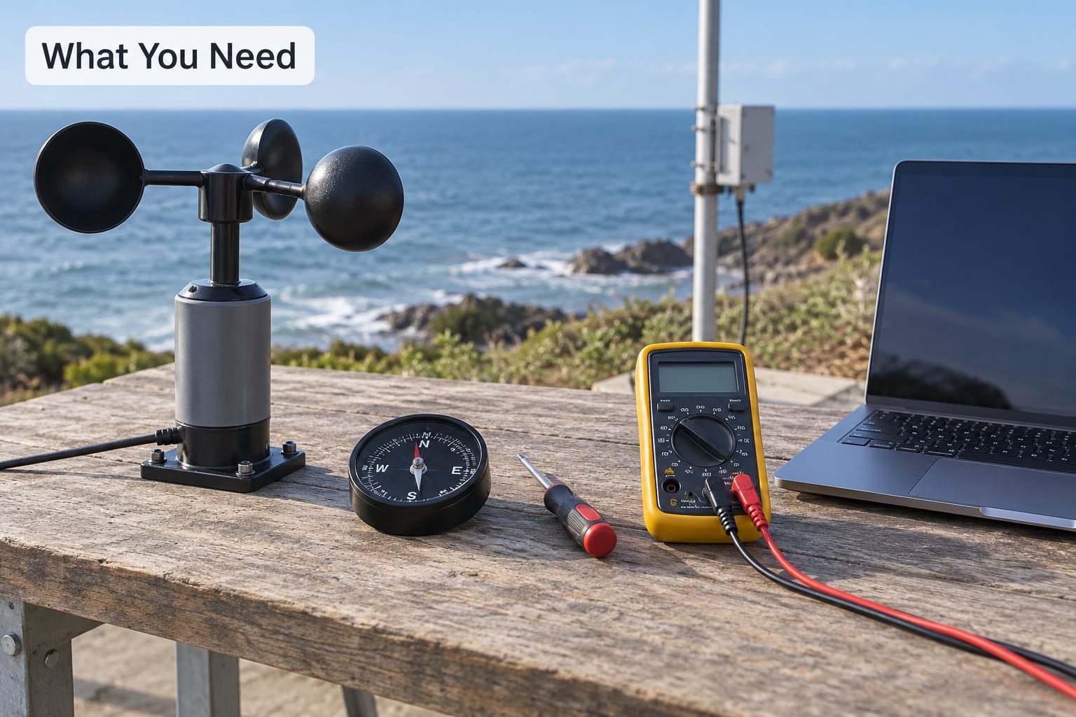
Calibration is a comparison job, so the list of tools is mostly about having something trustworthy to compare against. Gather these before you start.
- The sensor manual. It tells you which calibration constants the instrument accepts, how to enter them, and whether the process is factory-only. Some units expose nothing but a fixed trim screw.
- A reference. This is the honest part. Options in descending order of confidence: a recently calibrated reference anemometer, a calibrated anemometer you co-locate with yours, or a documented airflow such as a windless day with a towed vehicle at steady speed.
- A heading source. A magnetic compass with a stated deviation card, a handheld GPS bearing, or your boat’s own heading sensor.
- Logging software or a data logger. A laptop with a serial or USB capture tool, SignalK, or whatever reads your NMEA 0183 sentences. Eyes and a stopwatch are not enough once you are past 5 m/s.
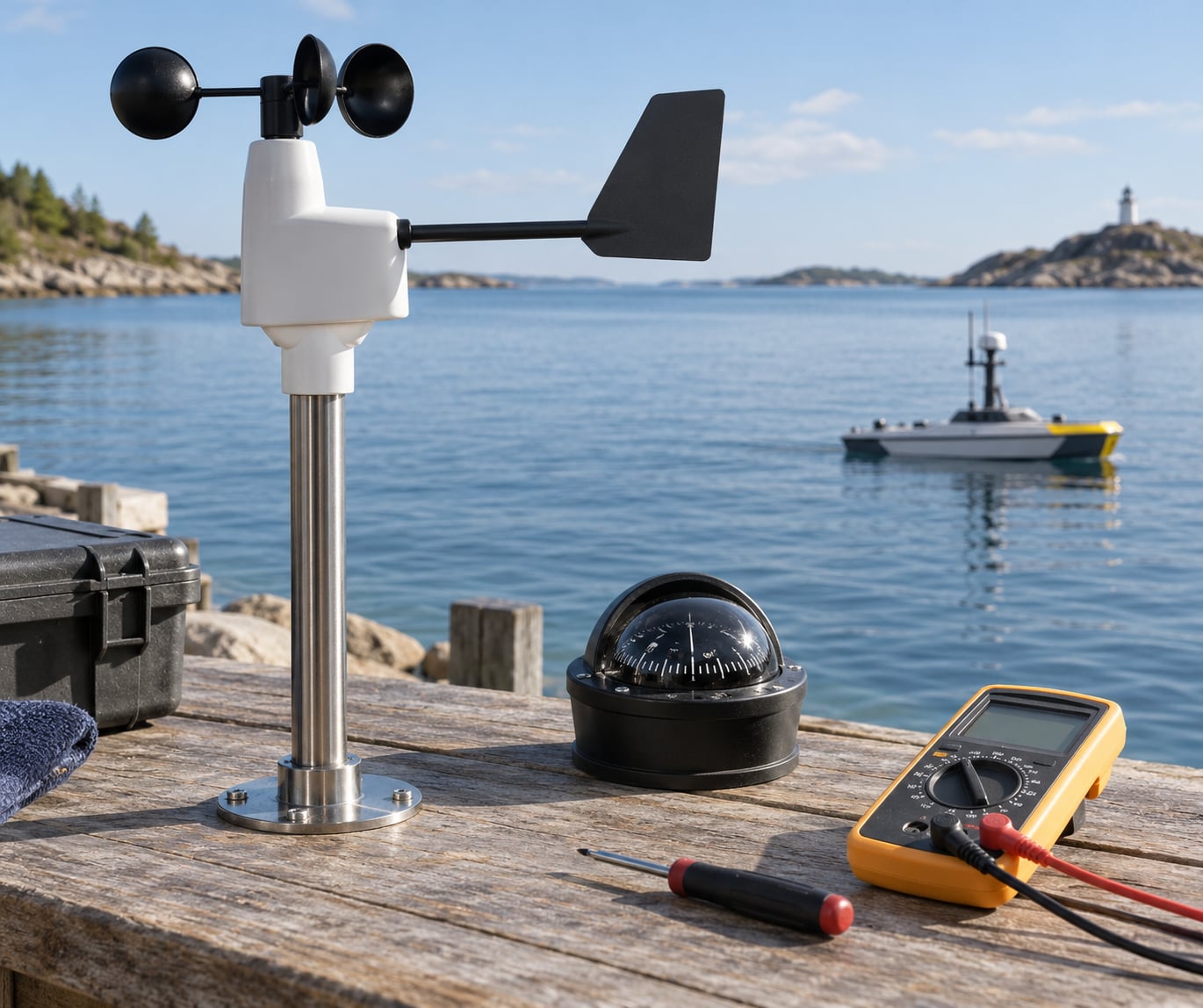
- Basic tools. Multimeter, small screwdriver set, cable ties, thread lock, mounting bracket, and a spare length of sealed cable.
- A stable test location. Open, unobstructed airflow, and a place where the sensor can sit at its final mounting height.
One more item worth adding: a copy of the calibration procedure your reference instrument came with. If it was calibrated by a lab under ISO/IEC 17025, that paperwork tells you the uncertainty you are working against.
Step-by-Step: How to Calibrate a Wind Sensor
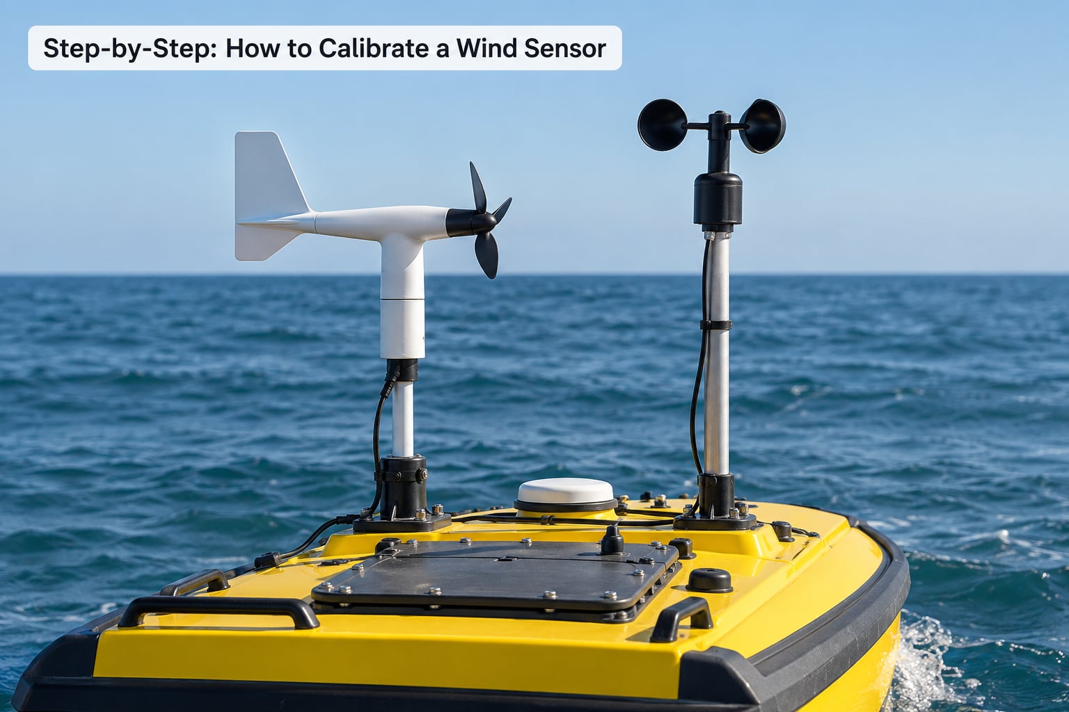
1. Identify the sensor and its calibration requirements
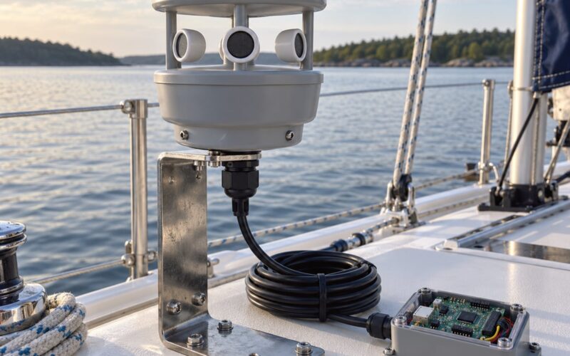
Read the label first. A three-cup anemometer, a wind vane, an ultrasonic head and a hot-wire probe all look like “a wind sensor” on a parts list and need completely different handling.
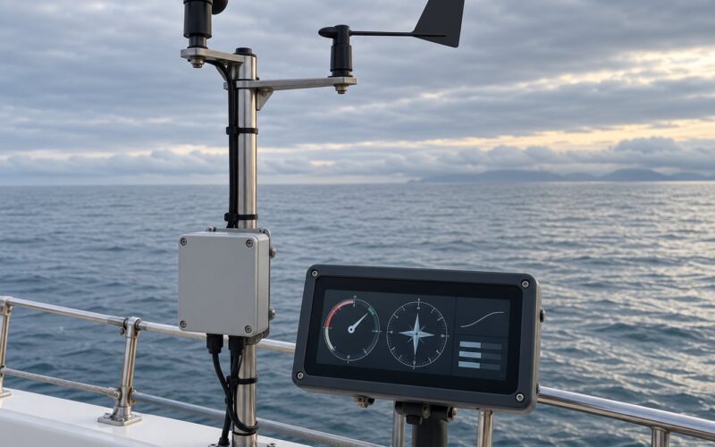
Then identify the output. Cup anemometers typically emit pulses or a switch closure per rotation, so your logger has to count revolutions per second and convert. Vanes usually give an analogue voltage, a potentiometer position, or an NMEA sentence. Ultrasonic sensors output digital packets, often NMEA 0183, with speed and direction already computed from time of flight.
Note the manufacturer’s stated accuracy and the calibration range it was tested over. If the manual says 4 to 16 m/s, do not expect meaningful results at 0.5 m/s.
2. Check power, wiring, and signal stability
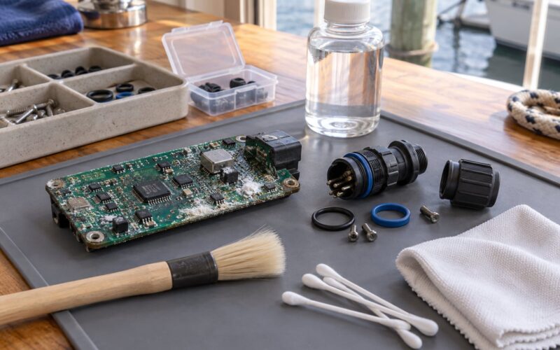
Most “calibration failures” are electrical faults. Check polarity at the transducer, confirm the shield and ground are connected as the manual specifies, and inspect every connector for corrosion or water.
Power the sensor from a clean supply and watch the raw output for at least ten minutes before touching anything. A rotor count that jitters with no airflow, or a direction reading that wanders while the sensor sits still, is a wiring or grounding problem, not a calibration problem.
Mains-frequency noise around 50 or 60 Hz, or ripple on the supply, shows up as a sensor that will not hold a zero. Fix that first.
3. Establish a stable calibration reference
Your reference has to be better than the sensor you are correcting, and it has to see the same air. Co-locate the two at the same height, within about a metre, with no mast, stay or hull between them.
For a boat, run the comparison underway in open water away from the lee of the hull. Record air temperature and barometric pressure at the same time as each pair of readings — air density feeds directly into pitot reference calculations, and an ultrasonic head’s speed-of-sound compensation depends on temperature.
Work in metres per second internally and convert for display. One metre per second is about 1.94 knots.
4. Zero or align the wind vane
Direction comes first because it is the easiest thing to get right. With the boat stationary and the wind steady, note the compass heading and the sensor’s reported direction.
Work out the offset as the difference between them, and add or subtract that value in the instrument’s calibration menu. On Raymarine instruments the procedure is in Chapter 7, section 2 of the manual, titled “Aligning the Wind Transducer”: motor the boat head to wind, confirm steady flow across the transducer head, and hold until the reading settles.
Recheck the offset after the mast is fully secured. Brackets move when you torque the bolts, and a loose clamp is a very common source of a heading error that looks exactly like a calibration error.
5. Calibrate wind speed readings
Speed needs both a zero and a gain. Start with the zero check: in genuinely still air — indoors, sheltered, or in a boat with the engine off and no wind — a healthy sensor should read zero and stay there. A cup rotor that creeps is dragging in its bearings; a reading that sits above zero is an offset.
Then collect paired readings across a range of speeds, aiming for at least five points between the sensor’s low working limit and the top of the range you actually use. For each point, log the reference value and your sensor’s value.
Work out the gain by dividing the true speed by the indicated speed at each point, then average. If the ratios agree within a few percent across the range, a single scale factor is enough. If they drift with speed, the sensor is non-linear and a one-number correction will not fix it — that is a mechanical or firmware fault worth chasing.
Enter the values through the manufacturer’s interface rather than editing configuration files by hand, and write down what you typed before you save.
6. Verify direction and heading accuracy
Test at several headings, not just one. Take readings with the boat pointing into the wind, across it, and with the wind on the beam, then compare sensor direction against compass heading each time.
If the error is constant in every position, it is a simple offset and the correction from step 4 holds. If the error changes with heading, you are looking at magnetic deviation, local interference from steel deck gear, or the mast shadowing the compass. That is a compass problem, not a sensor problem.
Also compare direction against where the vane physically points. It should agree within a few degrees once the vane has settled, and it should stop hunting rather than swing across the bow.
7. Validate, save, and document the calibration
Run the whole comparison again after applying the constants. A calibration that only holds at one speed is not a calibration.
Judge it against a stated tolerance. IEC 61400-12-1 Annex F is the standard reference for cup anemometer work, and reference-grade practice sweeps from 4 to 16 m/s in steps of no more than 1 m/s, running both rising and falling passes so hysteresis shows up as a gap between the two directions.
Record the setpoint, the reference reading, your sensor’s reading, the difference and a pass or fail mark for each point. Note the air temperature, the mounting height, the reference instrument and its own calibration date, and the combined uncertainty.
Finally, set a recheck date and put the record somewhere you will find it. People who cannot prove when a sensor was last calibrated usually end up calibrating it again.
Common Mistakes
Nearly every calibration that fails, fails for one of these reasons.
- Calibrating a badly mounted sensor. If the bracket is wrong, the sensor is partly behind the mast, or the tube diameter is too small relative to the rotor, the calibration describes a machine you do not have. Fix the mounting first, then calibrate.
- Using a reference that is not a reference. A second cheap sensor from the same batch is not a standard. It is a comparison that tells you about agreement between two identical weaknesses.
- Tuning software to hide loose wiring. Chasing a fluctuating reading with an offset value until it looks steady hides a corroded connector or a bad ground.
- Measuring in turbulent air. Airflow off a bulkhead, behind a cabin top or alongside a stack is not the free stream. The numbers will not repeat.
- Adjusting from a single reading. One data point cannot separate offset from gain, and it cannot show you whether the sensor is even linear.
- Skipping the rising and falling sweep. Bearing friction makes the reading depend on whether speed is increasing or decreasing. A one-directional sweep hides that entirely.
- Forgetting to record the constants. The next person to open the menu, or the next firmware update, will change them and nobody will know what they were.
Two more worth calling out. Never calibrate an ultrasonic head in one temperature and use it in another without checking the sensor’s own temperature compensation, because speed of sound shifts about 0.6 m/s for every degree Celsius and an uncompensated head inherits that error. And on a boat, check the compass deviation card before you touch the wind instrument — a direction error that changes with heading is almost never a calibration fault.
Frequently Asked Questions
Can you calibrate a wind sensor without a known reference?
You can check it, but you cannot fully calibrate it. Without a reference you can still do the still-air zero test, check the rotor spins freely, and confirm the vane settles within a few degrees of where it physically points. Those catch mechanical faults. What you cannot do is set an accurate scale factor, because that requires comparing output against wind speed you already know. A towed-vehicle run at steady speed with GPS as the reference is the cheapest honest substitute.
How often should a wind sensor be calibrated on a sailing robot?
Twice a year is a reasonable default for an unattended autonomous platform, so before and after the roughest season, plus one check after any deployment in severe weather. Uncrewed surface vessels salt-spray and get knocked about, and a build that takes six months offshore cannot be monitored by eye. Tightly regulated work can demand far more often, sometimes quarterly or monthly. Log every deployment and any storm exposure, and recheck earlier after a collision, a mast rebuild, or a firmware change.
Do I need to calibrate a digital wind vane differently from an analog one?
The physics is identical, but the process differs. An analog vane gives you a raw voltage or potentiometer position, so you convert that to degrees, then work out the offset between your heading source and the reported direction, and store the correction wherever the signal is consumed. A digital vane usually reports direction in an NMEA sentence, so you apply the offset in software, either in the instrument menu or in the layer that consumes the data. Either way, test at several headings so a constant offset does not hide a heading-dependent error.
Why does my wind-direction reading not match the boat’s compass heading?
Four causes account for nearly all of it. First, true heading versus magnetic heading, and local deviation on the boat. Second, the transducer is mounted off the boat’s centreline or fore-and-aft axis, so it reports wind relative to itself rather than to the bow. Third, magnetic interference from a deck-mounted transducer near steel or wiring is skewing the compass, not the vane. Fourth, the vane is still swinging and you sampled mid-swing. Check the compass against a handheld bearing first, since that tells you instantly whether the sensor is at fault.
What causes wind-speed readings to change after mounting the sensor?
Mounting changes the air the sensor sees. A mast or stay upstream cuts the wind and lowers the reading, and a tube or boom too close to the rotor disturbs it enough to change sensitivity. Height matters too, because wind speed increases with distance from the surface, so a sensor moved from two metres to six metres is now measuring a different wind. Bench calibration results do not transfer to a new height or a new mast. Recalibrate at the final mounting position, and record that height in your calibration record.
When should I replace or professionally service a wind sensor?
Replace it when the rotor drags in still air, when the vane no longer settles, when the housing is open or water is inside, or when repeated calibration cannot hold a gain across the range. Those are mechanical failures, and no amount of adjustment fixes them. Send it out for professional calibration when the measurement feeds a compliance requirement, a wind resource assessment, or a report that has to survive an audit, because that work needs traceability and a stated uncertainty. For everything else, a field method with a documented reference is honest enough.
Conclusion
Start with the still-air zero check and a wiring inspection. Those take five minutes, need no reference equipment, and they rule out the faults that look like calibration problems.
After that, compare against the best reference you can actually get, hold the sensor at its final mounting height, and record every setpoint, reference reading, test reading and difference along with the air temperature and mounting conditions. Write down the offset and scale factor you applied.
Follow the manufacturer’s manual for how to enter those constants, and recalibrate after any remounting, mast work, firmware change or severe weather. If the measurement has to be defensible to someone else, send the sensor to an accredited lab that works under ISO/IEC 17025 and can state its measurement uncertainty.