A watertight shaft seal is a mechanical barrier fitted where a rotating shaft passes through a stationary housing, built so water cannot travel along the shaft while the shaft still turns with low friction. Knowing how to make a watertight shaft seal comes down to four things: choose a seal system that matches the exposure, prepare both mating surfaces properly, hold the joint concentric while it cures, then prove it under test before it goes anywhere near salt water.
The honest answer is that a shaft seal is near-watertight, not perfectly watertight. The engineering goal is a controlled drip you can live with, not zero. On a conventional packing gland, owners on sailing forums treat roughly two drops per minute at rest as design intent rather than a defect.
Budget for most of a day. A bonded or potted seal on a shaft under 2 cm takes two to three hours of work plus cure time; a packless mechanical face seal on a stern tube is a longer job because alignment and plumbing decide whether it holds.
Table of Contents
What You Need
Start with the shaft and housing, because everything else is chosen around them. A shaft that runs a metre of open water, rotates at speed and sits under hydrostatic load needs a different answer than a static penetration on a slow-moving sensor pole.
Materials and consumables
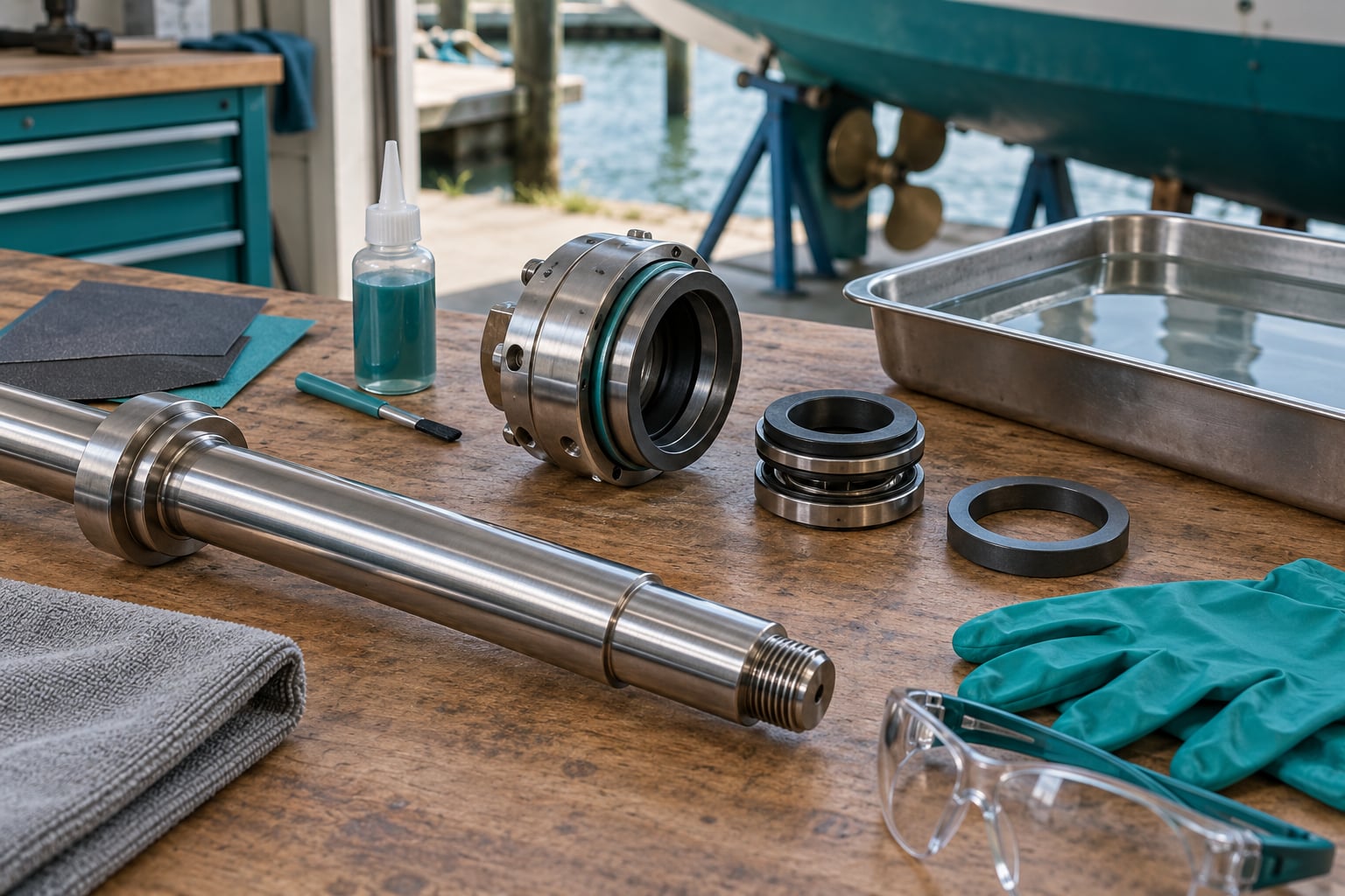
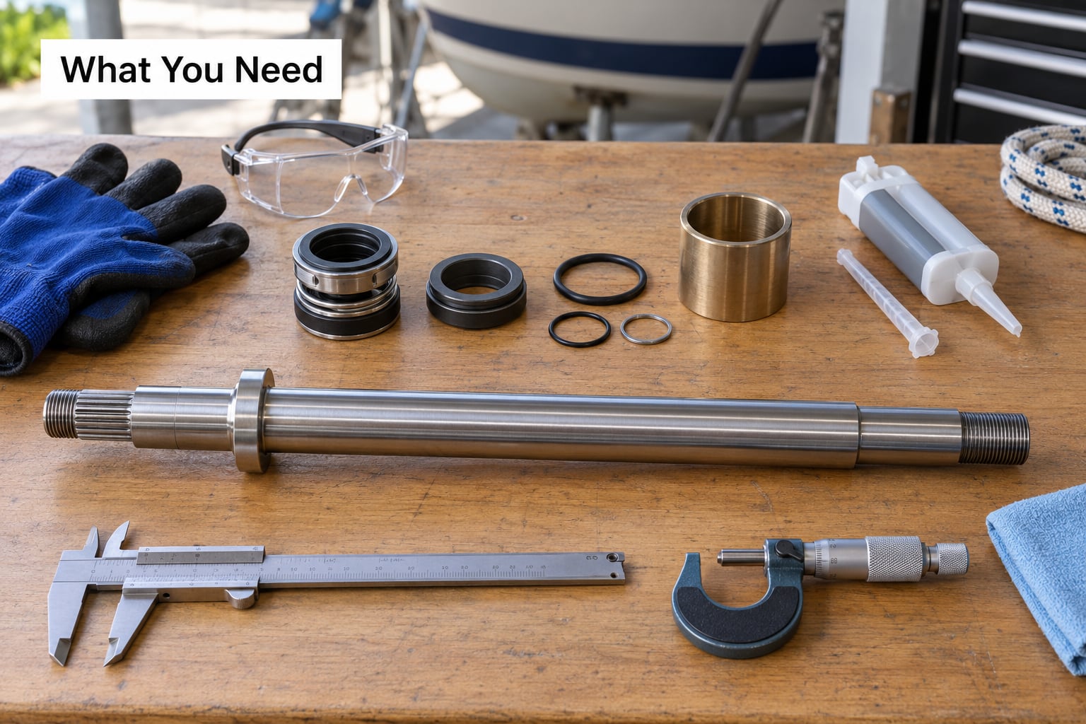
Collect the shaft or mating journal, the housing or tube it passes through, the seal components for that diameter, and the bonding or bedding compound the seal manufacturer specifies. Buy the adhesive in the exact viscosity and quantity the seal system calls for, since more is not better and squeeze-out under load is a common failure.
For surface preparation you want a degreaser that removes salt and petroleum residue, fresh abrasive at around 600 to 1200 grit wet-dry, masking tape, clean lint-free wipes, and a drying source. A chamfer tool or fine file handles the lead-in edge. Solvent wipes get you partway; they do not replace mechanical cleaning.
Fasteners, tools and safety gear
You need a micrometer or vernier caliper, a straightedge and feeler gauges, and a dial indicator if you can borrow one. Runout is the number that predicts whether a seal survives, so measure it before you commit to a seal system rather than after it fails.
Bring nitrile gloves, eye protection and a respirator if the bonding system calls for one. Work in a ventilated space and follow the manufacturer’s safety data sheet, not a forum habit. Keep petroleum grease, silicone spray and household sealant off the joint unless the manufacturer explicitly permits them.
How the choice depends on the joint
Seal choice follows shaft diameter, exposed length, speed, depth and the type of duty. A packing gland suits a slow shaft with a serviceable tube. A spring-loaded lip seal suits a clean shaft with no pressure on the dry side. A packless mechanical face seal suits a fast shaft with a dry bilge. A bonded or potted collar suits a short static penetration or a shaft too rough for a lip, and a labyrinth seal suits a rough shaft where zero drag matters more than zero water.
Decide whether the seal is static, rotating or a face seal before you cut anything. Each one asks for a different surface, a different tolerance and a different test.
Step-by-Step: How to Make a Watertight Shaft Seal
The procedure below runs in the order that saves time. Measure first, prepare second, align third, test last. Skipping any stage usually costs more than doing it properly, because a bonded seal that has cured into a misalignment cannot be corrected without cutting it out.
Measure the Shaft and Select the Seal System
Measure the shaft diameter, the housing bore, the seal width, the available clearance and the shaft runout before you choose anything, because these five numbers decide which seal system will actually work. Shaft diameter sets the seal size and the compression range. Housing bore sets whether the seal fits at all. Available clearance decides whether a bonded collar will bind the shaft once it expands. Runout sets whether a lip seal will ride evenly or saw into the shaft in the first hour.
Reading runout means clamping the shaft in the same bearings it will run in, putting the dial indicator on the journal where the seal will land, and turning it by hand through one full revolution. Any reading above a few hundredths of a millimetre is enough to explain a lip seal that leaks under way and looks fine at rest. On a stern tube, misalignment between the shaft and the shaft log is one of the most common causes of a new seal that fails within a season.
Compare the options honestly before committing:
| Seal system | Typical leakage | Water on the dry side | Serviceability | Best fit |
|---|---|---|---|---|
| Packing gland with fibre packing | Controlled drip at rest | Must be vented | Repackable on the water | Slow shafts, serviceable tube |
| Spring-loaded lip seal | Weeping, sometimes mist under way | Dry side must stay dry or flooded consistently | Replace cartridge | Clean shaft, no pressure differential |
| Packless mechanical face seal | Near zero when set correctly | Requires a vent line above the waterline on slow boats | Replace as a unit | Fast shafts, dripless bilge |
| Bonded collar or epoxy potting | Static, essentially zero | No pressure on the joint | Non-serviceable, cut out to replace | Static penetrations, rough short shafts |
| Labyrinth or slinger ring | Throttled, not sealed | Any | Cleanable | Shaft too rough for an elastomer lip |
Confirm the exact quantity of adhesive or bedding compound and the cure conditions the selected system allows before the joint is assembled. Manufacturers publish compression ranges keyed to shaft diameter and a full cure time, and those numbers are not interchangeable between systems. Follow the instructions for the unit in your hands rather than a generic figure.
How it worked: once the seal and the shaft size match and the runout reading is on paper, the rest of the build stops being guesswork.
Prepare the Mating Surfaces
Remove salt, grease, corrosion, loose particles and old adhesive from both mating surfaces, because no seal bridges a contaminated, damp, stepped, cracked or out-of-round joint. Salt crystallises out of seawater and stays invisible; it punctures elastomers and it stops epoxy from wetting the metal.
Work along the shaft with fresh abrasive, following the lay of the existing finish rather than crossing it randomly. A keyed or stepped shaft needs a chamfer or a lead-in so the seal slides on without catching and folding. Check the keyway: VIF’s replacement guidance treats roughly a 0.1 mm groove depth as the point where a lip seal starts losing its seal line, and anything deeper argues for a shaft sleeve rather than another new seal.
Mask neighbouring surfaces before you bond. Adhesive that migrates into a rotating clearance turns a sealed joint into a seized one, and the failure looks like a bearing problem rather than a sealing problem.
Match surface roughness to the seal. A lip seal wants a smooth, consistent, non-corroded journal; an over-polished shaft can shorten seal life because the lip cannot hold a film there. Hardness matters too: seal materials are chosen softer than the shaft so the shaft is what wears, never the seal.
Dry everything fully before assembly, then check the shaft is dry all the way to the core. Solvent on the surface that has not evaporated will outgas under the adhesive and leave voids in the bond line.
How it worked: a clean, dry, chamfered shaft with no keyway damage is the single biggest predictor that the finished joint will hold.
Install and Align the Seal
Install and align the seal in one controlled operation, using only the quantities and cure conditions the selected seal system allows. Assemble the housing and shaft concentric before the bond sets, because alignment is impossible to fix once the adhesive has cured.
Keep the seal at its designed radial position so the mechanical clearance survives the cure. A bonded collar that touches the shaft gives you a seal that is tight at rest and binds as soon as the shaft warms and expands.
Watch for trapped air in the joint. Squeeze the components together slowly and evenly, or apply the compound in a way that displaces air toward an open edge instead of trapping it. A void in a bond line becomes a channel.
Tighten fasteners gradually and in a star pattern, not around the circle in sequence. Uneven tightening shows up as a joint that is tight on one side and open on the other, and it is the usual cause of a leak that moves around the circumference as the boat moves.
Check concentricity before the adhesive sets: rotate the shaft by hand and confirm the gap to the housing is even all the way around. On a face seal, misalignment is what makes a carbon face wear into a wedge and mist under way. Also confirm the seal is free to float axially, since a floating carbon flange is designed to follow small variations in shaft position.
How it worked: even hand rotation with a steady drag and no tight spot means the joint is concentric before the clock starts.
Cure, Run, and Leak-Test the Joint
Cure, run and leak-test the joint in a fixed sequence: full manufacturer-specified cure, then inspection, then a controlled static water test, then a low-speed run, then a normal-speed run. Skipping the static test is how a joint that weeps on the dock becomes a joint that sprays at speed.
Let the joint cure for the full time on the data sheet, at the stated temperature. Fast cure under a lamp or a warm room gives you a bond that looks finished and peels later. After curing, inspect the joint line for voids, squeeze-out outside the designed area, and any movement you can see.
Run a controlled static test next. Flood the housing or tube to a defined level, hold it, and watch the joint. Mark the waterline on the tube so a slow seep is visible. On a boat, a seacock at the shaft log makes this test fast and repeatable; on an underwater vehicle, a bench tank test at the design depth does the same job.
Then run at low speed and check again before you go to normal operating speed. Mist at low speed usually means a lubrication or clearance problem. Squeal means the faces are running dry and the carbon can be damaged in minutes, so stop and fix it. Heat at the housing near the seal points to alignment or preload, not to the seal material.
Record the result while you watch it: drips per minute at rest, whether the mist appears under way, and housing temperature after ten minutes of running. Those three numbers make the next diagnosis fast instead of guesswork.
Map the symptoms back to their causes and the fault is usually one of four:
| Symptom | Likely cause | Correction |
|---|---|---|
| Drip at rest only | Vent blocked or below the waterline, or packing needs a further increment | Raise the vent above the waterline, then add compression in small steps |
| Mist or spray under way | Insufficient compression, debris between the faces, or shaft misalignment | Add compression in small steps, clean the faces with a rag while flushing with water, re-check runout |
| Squeal under load | Faces running dry | Stop running, restore the water or lube feed, re-check alignment |
| Sudden leak after service | Seal damaged on the chamfer or keyway edge during fitting | Inspect the shaft for a rolled lip or torn seal, fit a chamfer or sleeve |
| Water weeping past the lip | Corroded or out-of-round journal | Polish or sleeve the shaft, then fit a new lip |
How it worked: a recorded drip rate at rest and a mist check under way give you a pass or fail line, which none of the generic guides publish.
Common Mistakes
Most failed shaft seals trace back to one of nine mistakes, and each one has a straightforward correction.
Contaminated or damp mating surfaces. Salt, grease and moisture prevent bonding and destroy elastomers. Degrease, abrade, rinse and dry fully, then assemble while the surfaces are still clean and dry.
Wrong seal geometry for the shaft. A seal sized to the tube rather than the journal will never preload correctly. Match the seal to the measured shaft diameter and confirm the housing bore before fitting.
Excess adhesive. Too much compound squeezes out, migrates into the clearance and glues the shaft to the housing. Use the quantity the system specifies and let squeeze-out go where it is designed to go.
Trapped air in the bond line. Voids become leak channels. Assemble slowly and evenly so the compound displaces air toward an open edge, and avoid stabbing and reseating the parts once they are together.
Uneven tightening. Tightening around the flange in sequence produces a joint that is tight on one side and open on the other. Work in a star pattern in small increments.
Excessive shaft runout. A lip riding an out-of-round journal saws a groove and then leaks worse than before. Measure runout in the installed bearings and correct the alignment first.
Curing too soon. Handling or running a joint before the full cure time gives you a bond that looks finished and fails later. Respect the specified cure time at the specified temperature.
Ignoring pressure and movement. A seal designed for a dry side does not like being alternately flooded and dry, and a static seal is not asked to flex with a rotating shaft. Match the seal architecture to the duty.
Testing at full speed before inspection. Running hard with an unverified alignment or dry faces turns a small problem into burned carbon and a ruined rotor. Static test, low speed, inspect, then normal speed.
A marine-service habit worth building in: inspect the joint at every haul-out and flush the raw water feed and any flush passages on the same schedule. Owners who flush the passages report that leaks from debris between the carbon face and the rotor have been cleared without removing the unit. Salt deposits around the bellows and hose clamps tell you the joint has been sitting wet, which is where corrosion starts.
For underwater robotics, the same logic applies at depth. Seawater pressure rises by roughly 10 bar for every 100 metres, and that pressure acts on the dry side of the joint, so a seal that works at the surface has less margin with every metre of depth. Test in a tank at the design depth before launch rather than finding out in the water.
Frequently Asked Questions
What material is best for a marine shaft seal?
In seawater, the pairing that works best is a carbon-graphite face against a stainless steel rotor, because carbon wears predictably and takes the abrasion that would otherwise attack the shaft. For a lip seal, nitrile handles ordinary salt water for short exposure, while Viton FKM suits hot or chemically aggressive service. Choose the seal material softer than the shaft so the shaft wears first, and match the material to fluid temperature and chemistry rather than to brand.
Can I use epoxy to seal a shaft inside a housing?
Yes, as long as the epoxy is a static seal only and the shaft does not rotate through it. Epoxy is useful for short static penetrations, potted sensor housings and shafts too short or too rough for a lip. It cannot bridge a stepped, cracked or out-of-round shaft, and it must never be applied across a rotating clearance, where it will lock the shaft and then shear. Leave the manufacturer clearance intact and cure fully before running anything.
How do I test a shaft seal for leaks before launch?
Flood the housing or stern tube to a marked level and hold it while the shaft sits static, then check the joint for movement in the waterline. Next run the shaft at low speed and check again before going to normal operating speed. On a boat, fit a seacock at the shaft log for a fast repeat test. For an underwater vehicle, run a tank test at the intended operating depth. Record drips per minute at rest and note any mist under way.
How much shaft runout is acceptable for a sealed joint?
Keep total indicator reading at or under a few hundredths of a millimetre across the journal where the seal lands. That is tight enough for a lip seal to track evenly and for a mechanical face seal to stay flat. Measure with a dial indicator while the shaft turns in the same bearings it will run in, since alignment measured loose on a bench says nothing about the installed joint. Correct any runout above that before fitting a new seal.
Should a shaft seal flex as the shaft rotates?
A little controlled flex is normal and expected, because every seal is designed to accommodate small movement as the shaft runs. A lip seal’s spring preload makes its lip deflect slightly against the journal, and a floating carbon flange is meant to follow small axial shifts. Continuous flexing is a different story: a seal that moves enough to feel free, or that leaves a visible gap, is misaligned. Fit it concentric, confirm even hand rotation, and let the design preload do the work.
To make a watertight shaft seal that holds, the first move is measurement, not adhesive. Confirm shaft diameter, housing bore, clearance and runout, then select a seal system that matches the exposure, pressure and rotation. Prepare both mating surfaces to a clean, dry, chamfered finish, hold the joint concentric through the full cure, and finish with a static test followed by a low-speed run before the shaft ever sees salt water.