A paddle wheel speed sensor measures how fast a hull moves through water: a bladed rotor spins in the flow, magnets embedded in the blades pass a fixed sensor once per revolution, and each pass produces one electrical pulse. How to build a paddle wheel speed sensor is mostly mechanical — get the rotor spinning freely, count clean pulses, then convert pulse rate into knots with one calibration constant. A careful first build takes an evening on the bench and a weekend in the water.
Owners who hit a dead log usually get stuck on the same two problems: they cannot identify the part, and they cannot explain a zero reading. Building your own sidesteps the first problem entirely. The second one comes down to signal quality and calibration, which this guide covers in detail.
Table of Contents
- What You Need
- Step-by-Step: Build a Paddle Wheel Speed Sensor
- Frequently Asked Questions
- Can I use a Hall effect sensor with an Arduino?
- What are the different types of paddle wheel speed sensors?
- Can you splice paddle wheel speed sensor wires?
- How do I calibrate a homemade boat speed sensor?
- Why does my paddle wheel speed sensor read zero?
- How accurate is a DIY paddle wheel speed sensor compared with GPS?
- Conclusion
What You Need
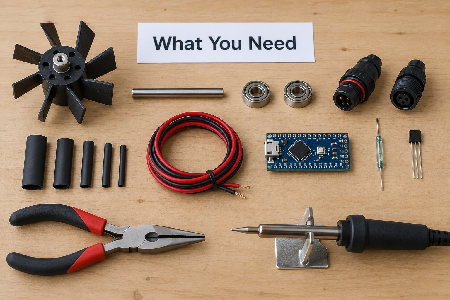
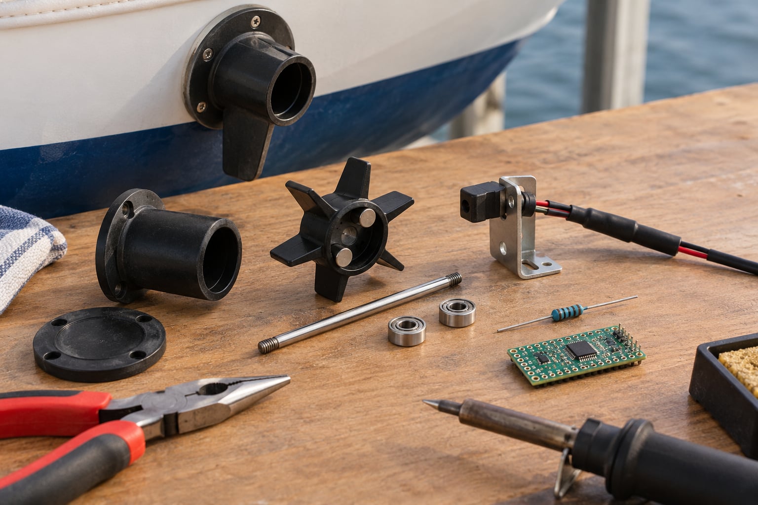
The rotor is the one part worth spending care on. A small paddle wheel rotor from a flow meter, or a machined or 3D-printed hub with cup-shaped blades, works well in low-speed water. Blades shaped like open cups bite the water better than flat paddles and slip less at low velocity.
For the shaft, use 6 mm stainless steel rod rather than brass or mild steel. It resists corrosion and does not bend when the rotor hits something. Two miniature bearings or sealed ball bearings support the ends and take the side load that kills plain bushing wheels.
Magnets matter more than most guides admit. Small neodymium discs or pot magnets, 3 mm to 5 mm across, pressed into the blade hubs, give a strong enough field for a reed switch at a realistic gap. Buy a couple of spares because one dropped into a drain is a bad afternoon.
For sensing, pick one of: a normally open reed switch, a Hall effect switch, an optical interrupter, or a magnetoresistive sensor. All four work; they differ mainly in power draw, minimum rotation rate, and how they behave in salt water. Step 1 covers the choice.
For electronics, plan on a microcontroller board with at least one interrupt-capable pin, a resistor kit, a small op-amp or comparator if you use a passive coil, a Schottky diode, a fuse or PTC, and a decoupling capacitor close to the sensor supply. Add a multimeter, a soldering iron, heat-shrink tubing, self-amalgamating tape, marine-grade stranded wire, and a strain-relief point for every cable that passes through a bulkhead.
Step-by-Step: Build a Paddle Wheel Speed Sensor
Step 1: Choose the Sensor Mechanism
There are two families here, the same division you run into when someone asks about the two types of speed sensors in a car. Active sensors are powered: a Hall effect or magnetoresistive part runs on 5 V and pushes a clean logic-level pulse out. Passive sensors generate their own signal: a reed switch is just a magnet-operated contact, and a coil-and-armature design induces a small voltage spike as the magnet passes.
Reed switches are the classic choice for a DIY boat speed log. They draw no current except at the moment of switching, which is why they appear in installations that care about battery drain. Their two limits are a minimum rotation rate — a reed switch will simply miss fast-passing magnets below a few hundred RPM — and contact bounce, which produces phantom pulses if you count edges without debouncing.
Hall effect sensors solve both. They count every magnet pass with no minimum speed and no bounce, at the cost of a steady few milliamps. They also need a regulated supply and a pull-up resistor on an open-collector output. Magnetic immunity is good, but the semiconductor part still needs sealing against salt.
Optical interrupters work well in a clear tube and are cheap, but fouling and darkness change the reading, and they need clean alignment. Magnetoresistive parts behave like Hall sensors with better magnetic range and are harder to source at hobby quantities.
My rule: use a Hall effect switch for anything that must keep working unattended, and a reed switch for a low-power installation where you will inspect the rotor regularly. Skip the passive coil unless you are salvaging one; it works, but its output is a fraction of a volt and needs real conditioning.
Step 2: Build the Paddle Wheel and Shaft Assembly
Press or glue the magnets into the blade hubs so that every blade carries exactly one. Record the blade count, because that number is your pulses per revolution. Four magnets is a good starting point for reading down to roughly one knot.
Mount the rotor on the shaft with a light press fit and secure it with a grub screw or a dab of epoxy. Then check runout: spin it by hand and watch the tip against a fixed point. More than about a millimetre of wobble at the blade tips is what causes the sensor to drop pulses intermittently, and it is far easier to fix now than after the hull is in the water.
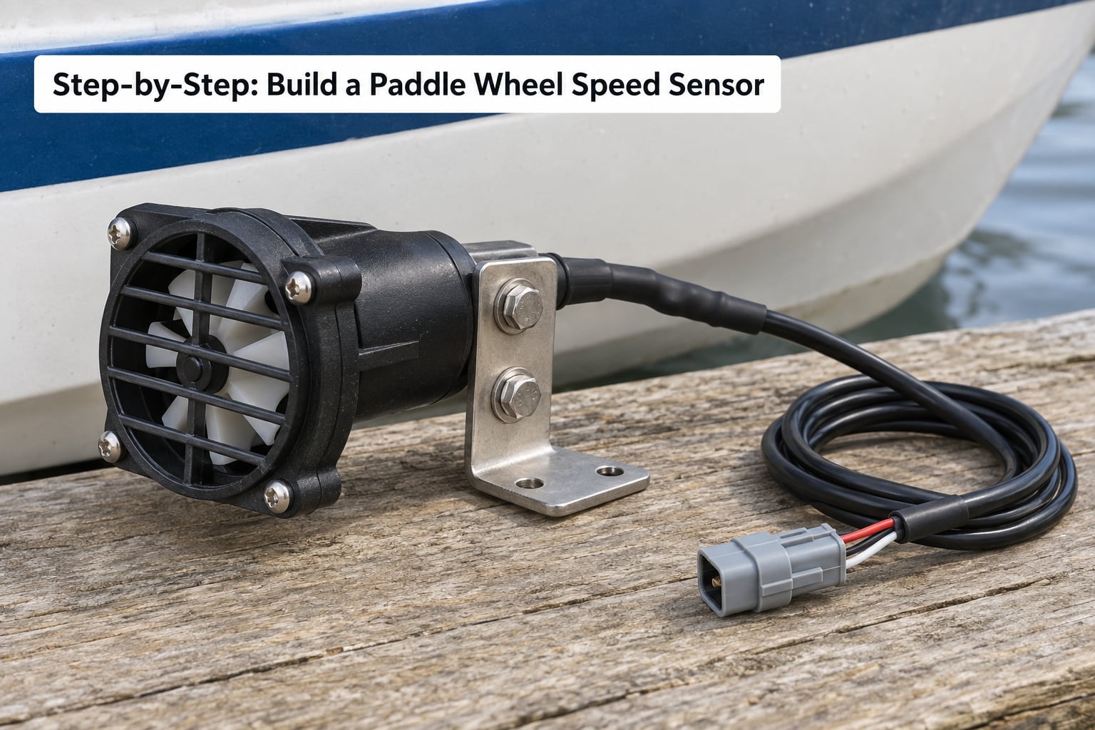
Fit the bearings in a bracket that holds the shaft parallel to the direction of flow. Off-axis by even five degrees cuts the effective flow across the rotor and costs you accuracy at low speed. Add a short protective grille of thin stainless rods around the wheel — it keeps weed and jellyfish out without noticeably changing the reading.
How do you know the mechanism is good? Blow or fan air across it and it should spin down smoothly and stop within a second. Any grinding, catching, or long coast means the shaft is bent or the bearing is binding. Fix that before wiring anything.
Step 3: Install and Wire the Speed Sensor
Mount the sensor on the same bracket, on the trailing side of the rotor, so the magnet passes directly across its face once per blade. Set the gap so the magnet engages reliably with the wheel spinning freely, not pressed against the bracket.
A Hall effect switch typically runs three wires: supply, ground, and output. Connect supply to regulated 5 V, tie ground to the sensor ground and the microcontroller ground at a single point, and add a 100 nF decoupling capacitor across the supply pins right at the sensor. If the output is open-collector, fit the pull-up resistor — 4.7 kΩ to 10 kΩ to your logic supply — at the microcontroller end, not at the sensor, so the line sees a clean rise.
Protect the supply. A Schottky diode in series plus a series fuse or PTC keeps a reversed battery or a load dump from taking the sensor out. This matters on a boat more than on a bench: the supply is a noisy 12 V system shared with pumps and solenoids.
Route the cable with a service loop, clamp it so it cannot chafe on a sharp edge, and take the strain off the joint at the connector. Splice with heat-shrink over a proper butt splice, then wrap the whole run in self-amalgamating tape. Keep splices above the waterline where you can get to them.
Step 4: Add Signal Conditioning and Data Output
A raw pulse train is the natural output of this sensor, and for most builds it is the right one. Count rising edges on an interrupt-capable pin, time the intervals with micros(), and divide the interval count by the number of magnets per revolution. That gives you rotation rate; one multiplication turns that into speed.
A frequency output, where the conditioning board converts pulses to a tone or a scaled analog voltage, is easier to read on a plain oscilloscope and on a controller with no interrupt pins to spare. The trade is that you hand the linearity problem to someone else’s board, and analog output in a wet, vibrating hull drifts.
Before you design the data side, look at what your controller actually needs. Most marine controllers and robotics boards want either a pulse count or an NMEA 0183 sentence, and a plotter will only show water speed if it receives the right sentence. The water speed sentence is VLW, which carries the measured water speed in knots along with a validity flag and a timestamp. NMEA sentences start with a dollar sign, so the raw sentence reads:
$VLW,023.4,V,,,,*hhEach sentence ends with a checksum of every character between that leading dollar sign and the asterisk. Get one field wrong and the plotter silently drops the sentence, which is the usual reason a homemade log shows up on the bench but not on the chart screen.
Step 5: Calibrate the Sensor for Real Speeds
Calibration is the step that turns pulses into knots, and skipping it is why homemade logs are distrusted. Use the run/measured-distance method: measure a known stretch of water, run at a steady speed, and count pulses.
- Choose a course of known distance — 100 m along a surveyed straight, a measured dock-to-dock leg, or GPS waypoints checked on land first.
- Pick one steady speed and hold it. Throttle changes during the run spoil the result.
- Count total pulses over the measured distance with the blades-per-revolution number from Step 2.
- Repeat the run three times and average the counts. Repeatability matters more than a single perfect run.
- Compute the constant: pulses per metre = average count ÷ distance in metres.
A worked example. Over 200 m you count 7,180 pulses with four magnets on the rotor. Pulses per metre is 35.9. A GPS says the boat made good 6.0 knots over ground on a still day, and your two readings agree closely at that point, so the water speed was 6.0 knots. The calibration constant is therefore 6.0 ÷ 35.9 = 0.167 knots per pulse per metre — multiply your measured pulses per metre by 0.167 in any future calculation.
Calibrate at two speeds if you can, one slow and one fast. Slip is proportionally worst when the boat is barely moving through the water, so a single fast-water constant will over-read near harbour. Note the weather: a run in current or wind against you is not a calibration, it is a comparison.
Afterwards, cross-check against GPS speed over ground. A log reads water speed only, so a steady difference between the two on a long straight passage is the current, set and drift. That difference is also how you catch a bad calibration before it reaches your log.
Step 6: Test, Seal, and Mount the Sensor
Test before it touches salt. Power the assembly on the bench, spin the rotor slowly by hand, and confirm the microcontroller counts a clean pulse per blade with no phantom edges. Then spin it fast with a cord drill and check whether the count still tracks — any dropouts here mean wobble or a magnet too close to the mechanical limit.
Submerge it in fresh water for an hour with the leads above the waterline. Watch for a steady pulse count while blowing across the rotor; any drift in the reading means water is getting into the sensor or along the shaft. Salt water is a harsher test, and if you have a tank, use it before the boat goes in.
Seal the electronics, not the water path. Pot the sensor and any board inside the hull with epoxy or a marine polyurethane, keeping the sensing face and the rotor exposed. A conformal coat on the board is not enough on its own — it does nothing for a connector or a through-hull joint. Fit a drip loop so water runs off instead of into the hull.
Mount the unit in the forward third of the hull, on the centreline where possible, with the shaft horizontal and clear of the propeller wash. Too far aft and you read disturbed water; in a propeller wash the pulse rate swings wildly at steady throttle. Fit a blanking plug any time the transducer is out of the hull, so the hole never sits open to the sea.
How do you know the install worked? Take the boat out at a steady cruising speed and compare log speed with GPS speed over ground. They should sit within a fraction of a knot in calm water, and the difference should grow slowly rather than jump when you change direction.
Common Mistakes
Slippage is the most common accuracy problem and the least visible. A rotor that spins freely on the bench still slips when the water flow is light, so readings below a couple of knots drift low. Cup blades, a longer wheel, and matching the rotor diameter to your typical hull speed all reduce it.
Shaft friction is the other big one. If the wheel needs a nudge to start, or coasts for several seconds, your reading is low at every speed. Bearings on both ends and a perfectly straight shaft fix this.
False triggers come from reed bounce or from floating magnet dust near the sensor. Debounce the input in software, cap the series resistance, and clear any stray filings off the rotor after machining.
Poor grounding shows up as erratic readings that change when the engine starts or when the thruster runs. Starve the sensor of a proper ground bond and you will chase the fault for months.
Air bubbles clinging to the blades reduce flow over the rotor and drop the reading. Wipe them off, check the orientation of the cup openings, and accept that rough water costs you accuracy.
Cable damage behind the panel is the leading cause of readings that work on shore and fail in the water. Chafe and corrosion hide under insulation, so wiggle-test the run while watching the count.
Wrong calibration is the last one and the easiest to fix. If your constant was taken at one speed in current, no amount of debugging will make it right. Re-run the measured-distance method and re-record the constant.
Frequently Asked Questions
Can I use a Hall effect sensor with an Arduino?
Yes, and it is the easiest reliable option. Wire supply to 5 V, ground to the Arduino ground, and put a 4.7 kOhm to 10 kOhm pull-up resistor from the output pin to 5 V if the output is open-collector. Add a 100 nF capacitor across the supply pins at the sensor, then count rising edges on an interrupt-capable pin. A Hall part has no minimum rotation rate, so it keeps counting at speeds where a reed switch would miss magnets.
What are the different types of paddle wheel speed sensors?
There are two families. Active sensors are powered: Hall effect and magnetoresistive parts give a clean logic-level pulse and need a regulated supply. Passive sensors generate their own output: a reed switch closes a contact when a magnet passes, and a coil-and-armature design induces a small spike. Reed switches draw no standby current, but they have a minimum rotation rate and suffer contact bounce. Optical interrupters are a third, cheaper option that is sensitive to fouling and darkness.
Can you splice paddle wheel speed sensor wires?
Yes for a two-wire passive coil or reed design, provided you use a proper butt splice, heat-shrink over the joint, and self-amalgamating tape around the run. Keep the splice above the waterline and leave a service loop at both ends. For a Hall sensor with three conductors, splice only if you can identify each wire at both ends. A single swapped conductor in a hall installation is a common reason the unit reads zero after wiring work.
How do I calibrate a homemade boat speed sensor?
Use the run/measured-distance method. Run over a stretch of known length at one steady speed, count total pulses, and divide by the distance in metres to get pulses per metre. Do three runs and average them. Then compare against GPS speed over ground on a still day: multiply pulses per metre by your verified speed in knots to get the calibration constant. Repeat at a second, slower speed, because slip makes a constant taken at speed over-read at low velocity.
Why does my paddle wheel speed sensor read zero?
A rotor that spins freely, looks undamaged, and still reads zero points at the sensor or the wiring, not the wheel. Pull the rotor out, rotate it 90 degrees past the sensor, and watch the count on the microcontroller. If it stays at zero, check supply voltage at the sensor, confirm the magnet gap, and look for a corroded connector or chafed cable. Fit a blanking plug whenever the transducer is out so the through-hull hole stays sealed.
How accurate is a DIY paddle wheel speed sensor compared with GPS?
A well-built and correctly calibrated one lands within a few percent of GPS speed over ground in calm water, and the gap widens at low speed where rotor slip dominates. Expect the least accuracy below one knot, in weed or heavy chop, and near a propeller wash. GPS measures speed over ground, which includes current, so the two readings are not identical even when the sensor is perfect. Use the difference to read current, not as an error.
Conclusion
Start with the mechanical side, because that is where most builds succeed or fail. Get a wheel-and-shaft assembly that spins freely with no wobble, confirm you get one clean pulse per blade, and only then think about sealing and mounting.
Calibrate over a known distance on a still day and write the constant on the housing. That one habit is the difference between a homemade paddle wheel speed sensor you trust for current and set, and one you only watch when GPS is off. Keep the mechanical checks at the start of every rebuild, however the electronics around it change.