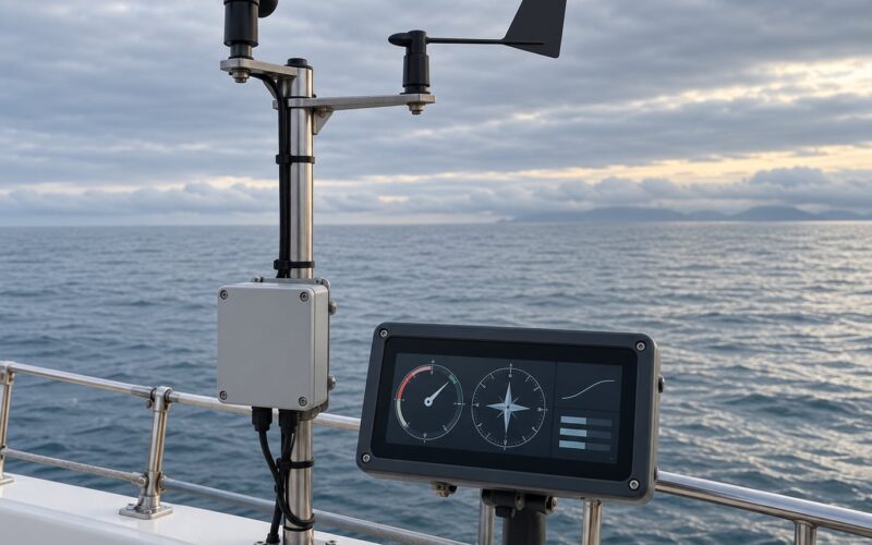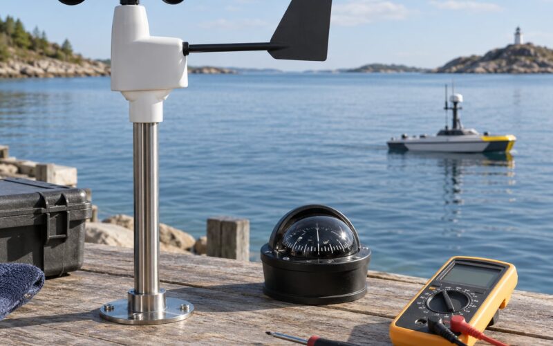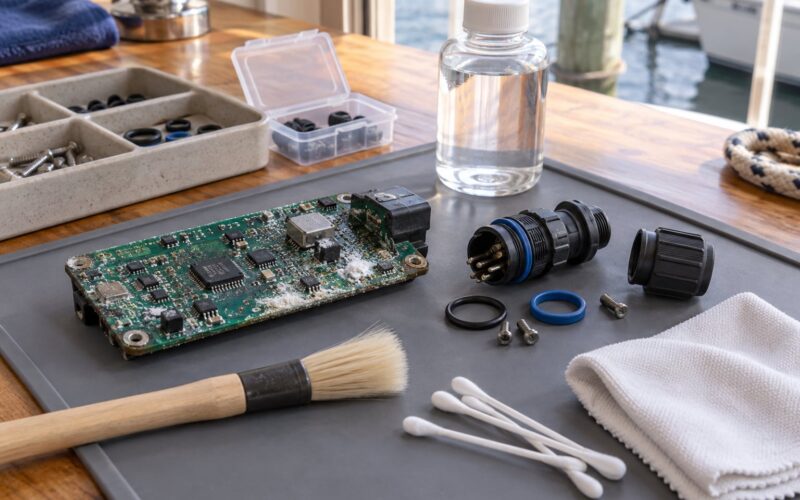
If you want to know how to make a wind sensor for a boat project, the short version is this: buy an ultrasonic wind sensor module, wire it to an ESP32 or an Arduino Nano, put the electronics in a sealed enclosure above the splash zone, mount the transducer array in clear air on a rigid bracket, then calibrate it against a reference before you trust a single number. Budget a weekend for the bench build and a second session for mounting and calibration.
The hard part is not the wiring. It is airflow, sealing and honest calibration. A cheap module on a bench will happily report numbers; bolted to a mast in a real wind with spray flying past, the same module tells you about your boat’s rigging as much as about the weather.
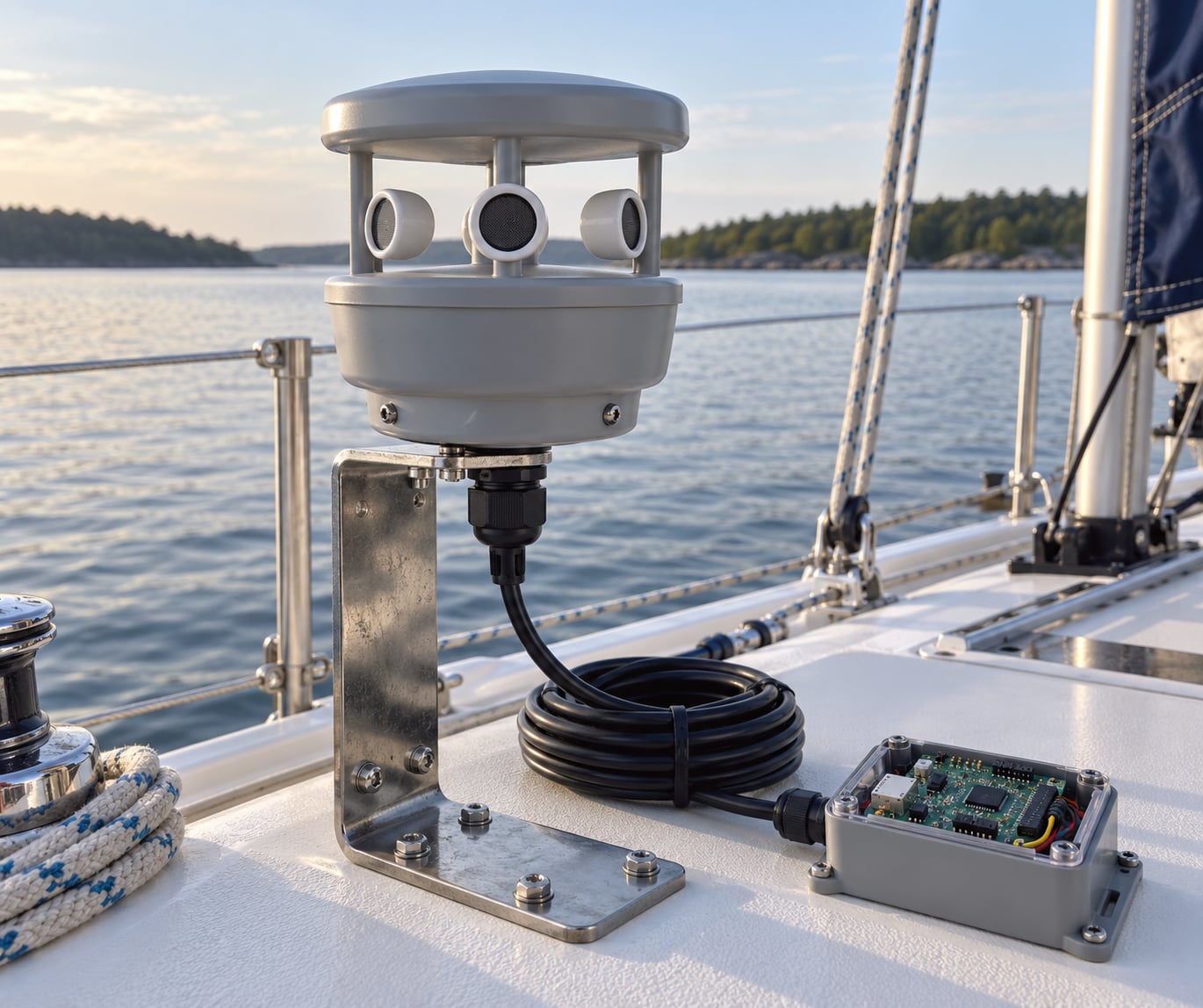
Here is what the finished unit looks like before we get into the steps:
| Target | Typical for a DIY build | Commercial reference class |
|---|---|---|
| Wind speed | 0 to 30 m/s range, roughly 1 to 2 m/s accuracy after calibration | 0 to 30 m/s with tighter tolerance |
| Wind direction | 0 to 360 degrees, practical resolution 5 to 15 degrees | 1 degree claimed, rarely achieved in real mounting |
| Update rate | 1 to 4 Hz is plenty for logging and most autopilots | 10 Hz for racing and research |
| Power draw | Typical small module plus regulator lands in the tens of milliamps | Documented, low single-digit milliamps for mechanical designs |
| Heel behaviour | Degrades as the array leaves vertical | Compensated or mechanically referenced |
Two of those rows deserve a warning before you buy anything. Manufacturers like to advertise 1 degree direction accuracy, and experienced builders on the open-source marine forums openly doubt it on a boat. The other is heel: an ultrasonic array is designed to sit perfectly vertical, and a heeling hull tilts it.
Table of Contents
- What You Need
- Step-by-Step: Build and Test Your Wind Sensor
- Common Mistakes
- Frequently Asked Questions
- Can I use an Arduino to measure wind speed?
- How can I make a DIY wind direction indicator?
- Is an ultrasonic anemometer better than a cup anemometer?
- Why does my DIY wind sensor read wrong when the boat heels?
- How accurate does a DIY boat wind sensor need to be?
- Can a cheap weather station wind sensor work on a boat?
- Conclusion
What You Need
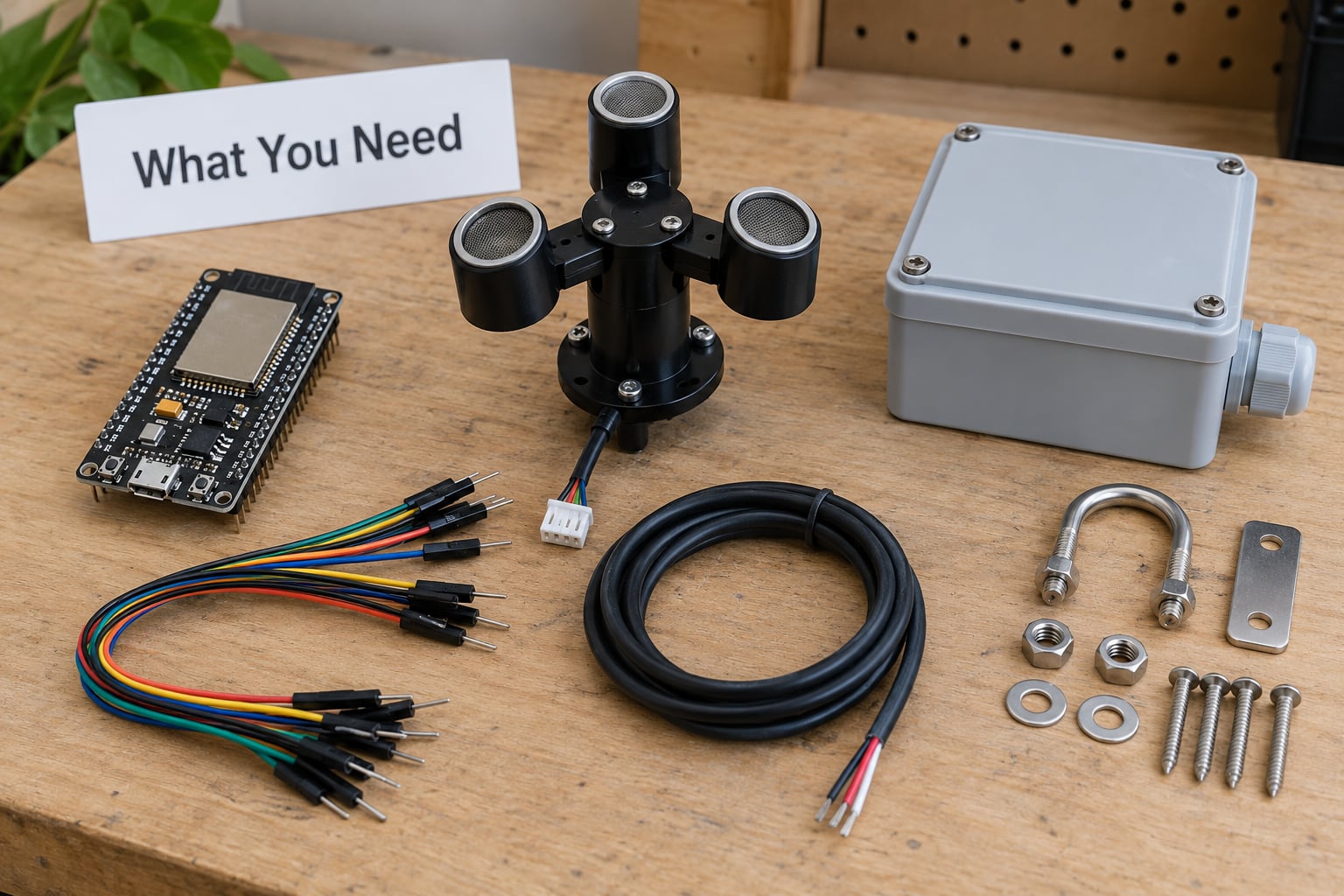
Every item below has a job. The electronics list is deliberately short because an ultrasonic module does the hard measurement for you.
The electronics
- Ultrasonic wind sensor module. Three or four ultrasonic transducers that time sound pulses between each other. This is the actual sensor. Make sure the datasheet states a wind range and a minimum wind speed threshold, because modules that claim 0 m/s resolution usually mean 0.5 m/s in practice.
- Microcontroller. An ESP32 for anything involving Wi-Fi, Bluetooth or logging; an Arduino Nano if you just want serial output and low power. Either is fast enough. You are reading a handful of numbers, not streaming video.
- Level shifting if needed. Many modules run at 5 V and their trigger pin is often 5 V tolerant, but check. If the module expects 3.3 V logic on a 3.3 V board, add a small level shifter rather than guessing.
- Decoupling capacitors. At least 100 nF at the module’s power pins, plus 10 uF bulk. Ultrasonic transducers pull short current spikes and a sagging rail produces exactly the kind of noise that makes readings wander.
- Data logger. A microSD card module, or serial over USB to a laptop or Raspberry Pi running SignalK. Logging matters more than most people expect, because calibration is impossible without a record of raw values.
The marine bits
- Waterproof enclosure. A sealed ABS or polycarbonate box rated for outdoor use, with a gasket. A 3D-printed housing works if you print it in a UV-stable material and seal it, but a commercial box is faster and cheaper than a failed print cycle.
- Rigid mounting bracket. Aluminium or rigid PVC, long enough to hold the sensor away from the hull. Do not mount the sensor head directly on a vibrating fiberglass surface.
- Marine-grade cable and strain relief. Multi-core stranded cable, tinned conductors where you can get them, IP-rated cable glands, and a drip loop at every entry point.
- Fastenings. Stainless steel, never galvanised. Salt water and galvanised steel produce a galvanic couple that eats your bracket from the inside.
- Power regulation. A 12 V to 5 V regulator rated for the total current, plus a fuse on the supply and reverse-polarity protection. A cheap linear regulator dissipates the difference as heat, so a switching module is kinder in a sealed box.
Minimum and recommended
The minimum build is a 3-wire ultrasonic module, an Arduino Nano, a sealed box, one cable gland and a USB cable for bench testing. It will produce wind speed and relative direction.
The recommended build adds an ESP32, a magnetometer or an I2C compass for heading reference, a microSD logger, a proper 12 V regulator with fuse and reverse protection, and a stainless bracket tall enough to clear the boat’s own turbulence. That combination is what turns a party trick into an instrument.
For a donor-based approach, a consumer weather station head is a real option. The open marine hardware community has published conversions that take a cheap W132-type station head and put it on a NMEA2000 bus with a small microcontroller. It is a good build for someone who wants a working instrument today and does not want to write time-of-flight code.
Step-by-Step: Build and Test Your Wind Sensor
Choose the Wind Measurement Method
Ultrasonic anemometers are the right default for a compact boat project because they give you both speed and direction in one small head, with no moving parts to seize in salt water. The trade-off is rain, tilt and cost.
Cup anemometers with a wind vane are the mechanical option. A rotor spins faster as wind speed rises, a Hall-effect sensor emits pulses, and the microcontroller counts them on an interrupt-driven digital input. A vane points into the wind and a rotary encoder or magnetometer reports its angle. Mechanical units feel heel the way a sail does, which matters more than most spec sheets admit, and they are usually cheaper. The cups need regular cleaning and they have a starting threshold below which they simply do not spin.
Pressure-based differential sensors are accurate in still air and expensive. A weather-station donor head is the pragmatic middle path: someone else solved the mechanics, and you solve the interface. Signal-strength or Wi-Fi-fingerprint methods are a party trick, not an instrument. Do not build a control loop on them.
How to tell it worked: you should be able to state, before buying anything, whether you need speed only, speed plus relative direction, or true wind direction relative to the boat’s heading. That one decision determines the parts list.
Connect the Electronics Safely
Most three-wire ultrasonic wind modules use a trigger pin, a serial output pin and ground. Four-wire versions add a serial enable line. Read the module’s datasheet and follow the manufacturer’s pinout rather than trusting a silkscreen.
Match supply voltages exactly. A 5 V module on a 3.3 V board under-reads; a 3.3 V module on a 5 V board can destroy a pin. Add a bulk capacitor at the module and a small one at the controller’s supply pin.
Module            ESP32 dev board
-----            --------------
VCC   ----------  5V (through 10 uF + 100 nF)
GND   ----------  GND
TRIG  ----------  GPIO 17
UART  RX  ------  GPIO 16   (controller TX -> module RX)
UART  TX  ------  GPIO 4    (module TX -> controller RX, level-shifted if required)
Note the crossover. Serial is a conversation, not a monologue: your TX goes to the module’s RX and the module’s TX comes back to your RX. Wiring them the obvious way gives you a board that boots fine and reports nothing, which is the single most common first-build failure.
On the 12 V side, run the supply through a fuse, then a reverse-polarity protection stage, then the regulator. Add a serial logging connection so you can watch the raw values coming out. Keep the bench power supply separate from the boat supply while you debug, because a short on a bench costs you a bench supply and a short on a boat costs you the boat’s battery bank.
How to tell it worked: with the module covered by your palm, the raw distance reading should change. If nothing arrives on the serial monitor, suspect the TX/RX crossover before you suspect the code.
Write the Wind-Speed and Direction Code for Your DIY Wind Sensor
The module does the time-of-flight measurement. Time of flight is simply how long a sound pulse takes to travel between two transducers; the difference in arrival times in opposite directions tells you which way the air is moving and how fast. Your code reads numbers, rejects bad ones and converts them.
Four things the program must do:
- Reject invalid readings. Check the returned byte count and a sanity range. Zero distance or a maximum-code value means no echo came back, which happens in rain, in spray, or when the array is partly blocked. Drop those samples rather than plotting them.
- Apply the temperature correction. The speed of sound in air changes with temperature, so time-of-flight systems need it. Many modules handle this internally and say so in the datasheet. If yours does not, read temperature from a small sensor and correct before you convert.
- Convert to wind speed and direction. Most modules already report in m/s and degrees. If you are doing the conversion yourself from raw transit times, this is where the geometry lives: the angle between the transducer pairs gives direction, the transit difference gives speed.
- Timestamp and log. Stamp every sample, print it as CSV to serial or SD, and include a sequence counter so you can spot dropped samples later. Calibration depends entirely on having this record.
// Minimal ESP32 loop for a 3-wire ultrasonic wind module
// Assumes the module reports "speed, direction" in a single line.
#include <HardwareSerial.h>

HardwareSerial WindSerial(1);
const int PIN_TRIG = 17;
const int PIN_RX   = 16;
const int PIN_TX   = 4;
const int LED      = 2;

unsigned long lastTrigger = 0;
const unsigned long TRIGGER_INTERVAL_MS = 250;  // 4 Hz

void setup() {
  Serial.begin(115200);
  WindSerial.begin(9600, SERIAL_8N1, PIN_RX, PIN_TX);
  pinMode(PIN_TRIG, OUTPUT);
  pinMode(LED, OUTPUT);
}

void loop() {
  unsigned long now = millis();

  if (now - lastTrigger >= TRIGGER_INTERVAL_MS) {
    lastTrigger = now;

    digitalWrite(PIN_TRIG, HIGH);
    delay(3);
    digitalWrite(PIN_TRIG, LOW);

    unsigned long t0 = millis();
    while (WindSerial.available() == 0 && millis() - t0 < 200) {
      // wait up to 200 ms for the module's reply
    }

    if (WindSerial.available() > 0) {
      String reply = WindSerial.readStringUntil('n');
      reply.trim();

      // sanity gate: reject empty or out-of-range samples
      if (reply.length() > 0) {
        int comma = reply.indexOf(',');
        if (comma > 0) {
          float speed = reply.substring(0, comma).toFloat();
          int   dir   = reply.substring(comma + 1).toInt();

          if (speed >= 0.0 && speed <= 60.0 && dir >= 0 && dir < 360) {
            digitalWrite(LED, HIGH);
            // CSV with a monotonic timestamp, easy to import anywhere
            Serial.print(now);
            Serial.print(',');
            Serial.print(speed, 2);
            Serial.print(',');
            Serial.println(dir);
          } else {
            digitalWrite(LED, LOW);   // bad sample, do not log it
          }
        }
      }
    } else {
      digitalWrite(LED, LOW);         // no reply this cycle
    }
  }
}
If you run a SignalK server on a Raspberry Pi, the ESP32 can post readings as JSON instead of raw CSV. SignalK is the open JSON-based marine data format used by OpenPlotter and similar displays, and a single value is enough to light up a chartplotter gauge.
{"context":"environment.wind.speed","value":{"value":6.4,"units":"m/s"}}
{"context":"environment.wind.direction.bearing","value":{"value":214,"units":"deg"}}
{"context":"environment.wind.directionApparent","value":{"value":231,"units":"deg"}}
One important warning about the wireless route. Linux Wi-Fi stacks are not realtime-safe and can stall for well over a second under load. That is fine for a dashboard and fatal for a control loop. Anyone feeding an autopilot should use a wired serial or bus link and keep the wireless hop for display only.
How to tell it worked: point the array at an open fan, watch the speed value rise and fall as you change the distance, then turn the whole unit 90 degrees on the bench and confirm the direction figure changes by roughly the same amount.
Mount the Sensor Where Wind Is Undisturbed
This is the step that decides whether your readings mean anything. Every sail, mast, antenna, radar arch, canvas cover and rail creates its own turbulent wake, and the boat’s own wake is the biggest error source in the whole system.
Mount high and forward of anything that disturbs airflow, as far from the hull’s boundary layer as your boat allows. Keep it clear of spray, clear of engine and motor exhaust, and clear of the funnel. A rigid bracket is not optional: flex in the support changes the alignment of the transducers and quietly biases every reading.
Orientation has to be repeatable too. Mark the mounting face and the forward direction so reinstallation lands the same way every time. If you calibrate with the unit mounted, you can tolerate a small offset; if you calibrate on a table and then mount it crooked, you will chase that error forever.
Keep the electronics above the splash zone even if the sensor head is rated for immersion. Water that gets in will not dry inside a sealed box, and condensation in there is worse than a few splashes because it sits on the board all season.
How to tell it worked: hold a hand anemometer beside the installed sensor in a steady breeze and compare. If the two disagree consistently by a fixed amount, that is a mounting or alignment problem, not a sensor problem.
Calibrate and Validate the Measurements
A new sensor is not accurate out of the box, and the datasheet does not promise it will be. Calibrate after mounting, because mounting is part of the measurement chain.
Wind speed. Put the sensor in front of a known airflow source with a reference anemometer beside it. A large fan on a known setting, or a second hand-held unit you trust, is enough. Take a spread of readings across the range you care about and record the raw counts per second or per sample.
Then fit a scale factor. Log both the raw value and the reference value for each point, and solve for the multiplier that makes the two agree. Store that factor in the firmware as a calibration constant instead of correcting in your head every time you look at the output. Repeat the test at low, medium and high wind, because cup anemometers are usually non-linear at the low end.
Wind direction. Zero the direction against a known bearing. Point the unit at a fixed landmark whose compass bearing you know, read the reported angle, and store the difference as your offset. Repeat at a second bearing to confirm the offset holds rather than drifting. Add a small deadband near zero so the value does not flicker between 359 and 1.
Heading tests. Slowly rotate the complete installed unit through a full circle on the boat. Real wind should stay constant while the reported relative direction tracks the rotation exactly. If the reported value jumps or the relationship is not clean, the mounting is loose or the transducers are partly blocked.
Uncertainty. Write down your number as a range, not a decimal. A hand-built unit that agrees with a reference within 1 m/s across the useful range is a good instrument. Treat anything below your reference unit’s own accuracy as noise and do not claim it.
How to tell it worked: you can state a single calibration factor in your firmware and one direction offset, and both numbers came from recorded data rather than guesswork.
Protect the Sensor on the Water
Waterproofing is not the same as immersion rating. A sealed box that survives a soaking will still fail if the water gets in and stays in.
Use a box with a proper gasket and cable glands rated for the entry size. Seal each cable entry with a compatible marine sealant, and leave a drip loop below the entry point so water runs off instead of following the cable in. Add strain relief inside the enclosure so a tug on the deck line cannot pull against a solder joint, and secure the cable run along the mast or rail with stainless clips rather than tape.
Conformal coating is worth it on the board but never on the transducers. Keep any coating off the acoustic faces; a film of coating across a transducer face kills the ultrasonic path quietly, and you will spend a day blaming the code.
Watch condensation. A sealed box that warms in the sun and cools at night will pull moisture from the air inside it. A desiccant pack or a small vent with a hydrophobic membrane is the usual fix. Do not simply leave a hole in the box; that trades condensation for a direct spray path into the electronics.
After the first month at sea, take the sensor down, rinse it with fresh water, look at the cable entries and the connector pins, and check the enclosure seal. Salt crystallises in places you will not think to look. If you use plugs rather than a permanent splice, remember that USB on a moving boat is a poor choice: corrosion and flex break it, which is why bus connectors with tinned wires are the community’s usual answer.
How to tell it worked: after a season in salt spray, the enclosure is still dry inside and the sensor still returns sane values on a windy day.
Common Mistakes
Almost every failed DIY wind sensor comes down to one of the following. The fix is usually cheap; finding the cause is usually the annoying part.
| Symptom | Likely cause | Fix |
|---|---|---|
| Board boots, no data ever arrives | TX and RX wired straight through instead of crossed | Swap the two lines. This is the most common build error there is. |
| Readings wander with no wind | Sagging supply rail, missing decoupling, ultrasonic interference | Add 100 nF plus 10 uF at the module, separate the transducer wiring from motor and thruster cables, and power from a clean regulator. |
| Readings drop out in rain or spray | Water on the acoustic paths shortens or absorbs the pulses | Accept the dropout, flag bad samples in firmware, and tilt the array slightly so water sheds. Do not seal the transducers; sealing makes it worse. |
| Direction is plausible but consistently wrong | Mounting rotated after calibration, or no heading reference | Zero direction against a known compass bearing with the unit installed, and store the offset in firmware. |
| Speed is systematically low or high | No calibration factor, or temperature not compensated | Run the reference comparison, fit a scale factor, and check whether the module applies temperature compensation internally. |
| Readings fall apart when the boat heels | Ultrasonic array tilted out of vertical, turbulence around the head | Add an IMU and compensate in software, or switch to a mechanical vane, which feels heel the way a sail does. Soft mounting makes it worse. |
| Board is damp inside after a month | Condensation in a sealed enclosure | Add desiccant or a hydrophobic vent membrane, and check the cable gland sealant. |
| Values stall or arrive in bursts | Wi-Fi or Bluetooth link used for a control loop | Move to a wired serial or bus link. Wireless is for dashboards only. |
| Bluetooth connects but the server sees nothing | Phone or tablet requires location services enabled for Bluetooth | Enable location for the device. This is intended platform behaviour, not a bug, and it negates the low-power benefit of the link. |
| Direction confused with boat heading | Mixing relative vane angle with compass bearing | True wind direction is relative angle plus heading. Compute both and publish apparent and true values separately. |
One testing tip that catches more bugs than anything else: before the boat ever moves, run a bench test suite while you deliberately misconfigure things. Cut the power for a second, wet your finger on the transducer face, tilt the unit 30 degrees, disconnect the temperature sensor. Watch what your firmware does with each. A logger that keeps reporting confident numbers when the sensor is obviously broken is worse than one that stops.
Frequently Asked Questions
Can I use an Arduino to measure wind speed?
Yes. An Arduino Nano or ESP32 is more than fast enough. With a cup anemometer that has a Hall-effect pulse output, count pulses on a digital input using interrupts and convert pulses per second to metres per second with a calibration factor. With a commercial analog anemometer, read the analog pin and map the voltage. Most of the work is calibration and wiring, not processing power.
How can I make a DIY wind direction indicator?
Mount a pointer or small vane on a magnetic rotary encoder or a magnetometer at the top of a short mast. Feed the encoder output to a microcontroller and add a separate compass or magnetometer for the boat’s heading. That lets you convert the relative vane angle into true wind direction. Zero the vane against a known compass bearing once the unit is installed, not on the bench.
Is an ultrasonic anemometer better than a cup anemometer?
Neither wins outright. Ultrasonic units give speed and direction in one head with no moving parts and no starting threshold, but they cost more, drop out in heavy rain, and lose accuracy as the boat heels. Cup-and-vane designs feel heel the way a sail does, are cheaper, and tolerate rain, but need cleaning and will not turn below their starting speed. Most makers end up choosing on mounting location.
Why does my DIY wind sensor read wrong when the boat heels?
Ultrasonic arrays are designed to sit perfectly vertical. Heel tilts the transducers, changes the geometry your firmware assumes, and puts the head in the boat’s own turbulent air. A mechanical vane has the same physical behaviour, so it stays honest. For an ultrasonic build, mount the array on a rigid vertical face, add an IMU, and rotate the measurement frame by the measured heel angle in software.
How accurate does a DIY boat wind sensor need to be?
For logging, sail trim feedback and a true-wind display, agreement within about 1 m/s and 10 to 15 degrees is plenty. For an autopilot in wind mode or dynamic positioning, treat anything under roughly 0.5 m/s as marginal, because that error feeds straight into steering decisions. Always state your result as a range measured against a reference, and never quote more decimals than your reference can support.
Can a cheap weather station wind sensor work on a boat?
Yes, and it is one of the fastest routes to a working instrument. Consumer weather-station heads use standard pulse and potentiometer outputs, so a small microcontroller can count the pulses, read the direction, and republish the data as NMEA0183 or on a SignalK network. Marine hardware communities have published working conversions of this type. The limitation is mechanical durability: the housing was not designed for salt spray or UV.
Conclusion
Start by deciding what will consume the data. An autopilot, a dynamic positioning loop, or a logger, because a wind sensor that feeds nothing is an expensive decoration.
Then buy the sensor head, wire the microcontroller on a bench, and prove the numbers before anything goes near the boat. Airflow matters more than silicon: a well-mounted mediocre sensor beats a perfect one bolted next to a sail. Calibration is the step people skip and the step that makes the difference, and marine sealing decides whether the build survives its first season.
Working through how to make a wind sensor for a boat project is only half the job. Before you let the finished unit steer anything, validate it against a reference in real conditions and record what it actually does, including the bad weather. That log is the only thing standing between a confident number and a useful one.