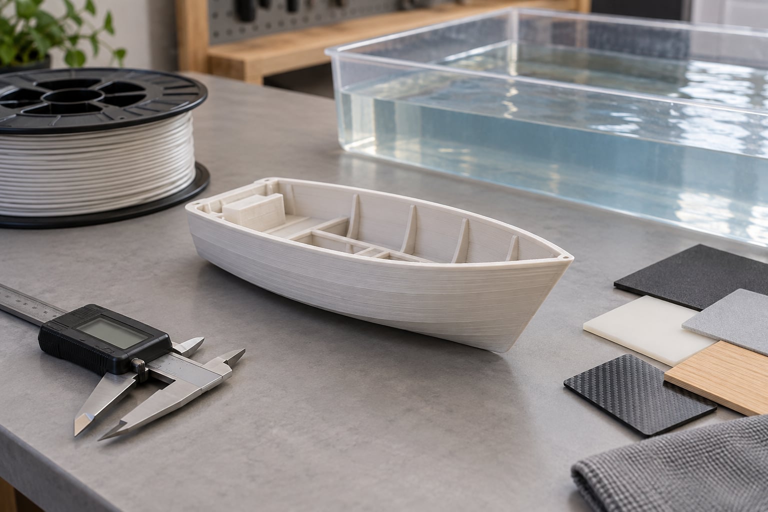
Yes, you can 3D print a boat hull, and a fair number of people have. The catch is scale: a desktop filament printer builds model boats, kayaks and unmanned surface vessels, while metre-scale hulls need large-format additive manufacturing and a lot more engineering. Printing a hull removes the mould, which is the biggest cost barrier in conventional boat production, but it swaps in problems of layer adhesion, print direction and post-processing.
This guide covers the choices that decide whether a printed hull floats, leaks, or cracks: which filament survives salt water and sun, how to design a curved hull so it prints without a support forest, how to seal the seams, and how to work out whether the thing will actually carry its motor and battery. Landmarks and material test data are included too, so you can see where the technology currently sits in 2026.
Table of Contents
- What Are the Best Materials for 3D Printing Boat Hulls?
- How Do You Design a 3D Printable Boat Hull?
- What Printer and Settings Should You Use?
- How Do You Make a Printed Hull Watertight?
- How Much Does 3D Printing Change the Boat’s Buoyancy?
- What Tests Should You Run Before Launching?
- Where Do 3D Printed Hulls Make Sense?
- Frequently Asked Questions
- Conclusion: Start With a Small, Testable Hull
What Are the Best Materials for 3D Printing Boat Hulls?
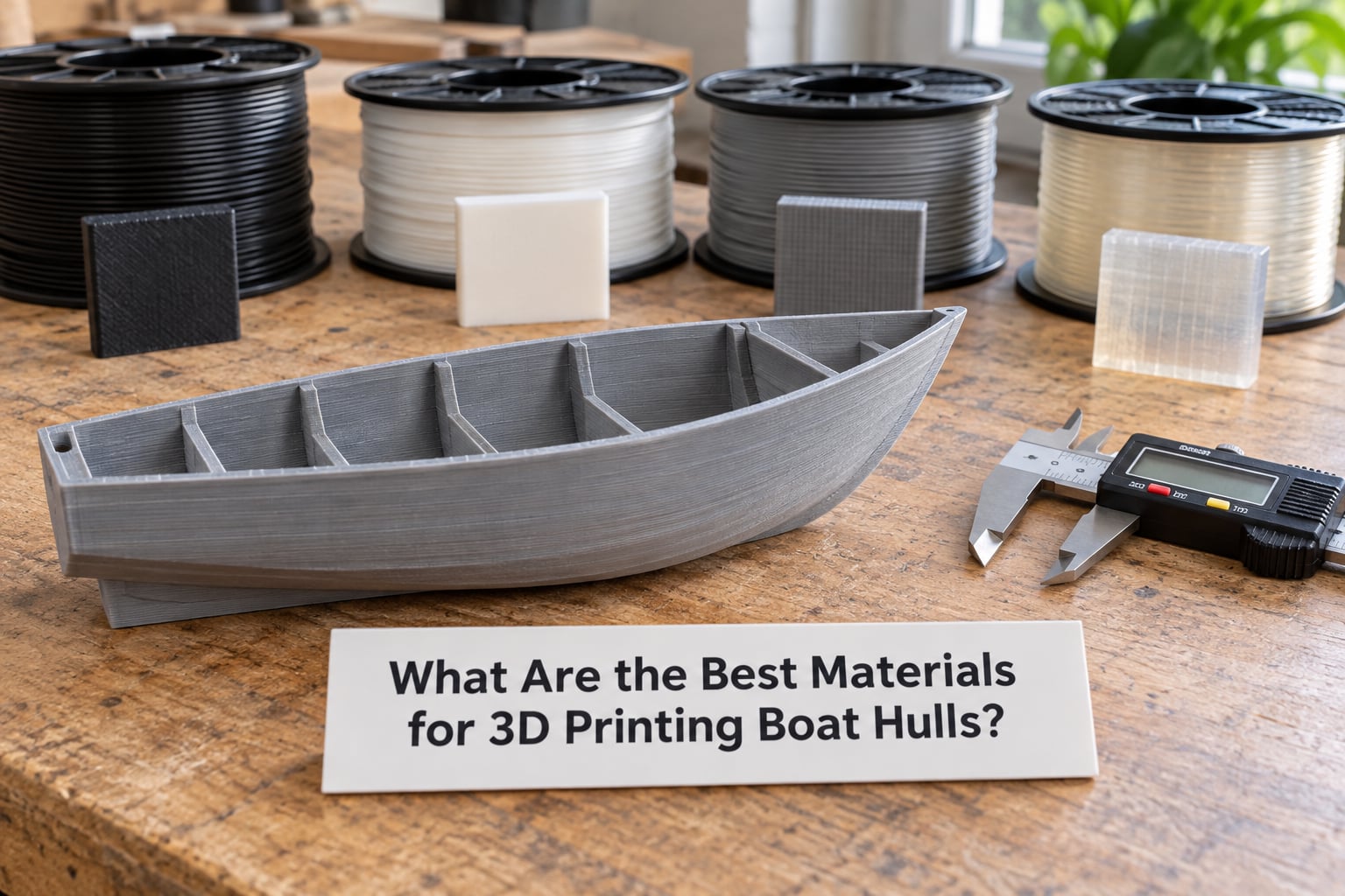
The short answer is ASA or PETG for anything that will see weather, and a fibre-reinforced thermoplastic if you have access to a large-format machine. The long answer is that every filament trades water absorption, UV stability and layer adhesion against each other, and no consumer filament is watertight straight off the bed.
PLA: fine for a model, wrong for a boat in the sun
PLA prints beautifully and holds detail, but it softens near the temperature of a hot car interior and has no useful resistance to water or UV. Use it for tank fittings, display models and anything that stays indoors. A hull printed in PLA and parked in the sun will go soft and brittle, and the surface will craze.
PETG: the default choice for small craft
PETG has low water uptake, decent layer adhesion and a usable temperature window on almost any machine. One builder on r/rcboats reported running PETG with no water infiltration from the hull as printed, and others in that same community use it for model boats that are sealed with paint. For kayaks, small skiffs and USV hulls, PETG is usually the right starting point.
ABS and ASA: tougher, but they need an enclosure
ABS is the classic boatyard answer, and ASA is its UV-stable equivalent. Both need a heated, closed chamber to print without warping, which rules out a lot of open-frame desktop machines. On r/3Dprinting, builders weighing PETG-HF against ASA for model boats tend to land on ASA for its UV resistance and flexibility, at the cost of longer prints and more stringy corners. If your printer is not enclosed, PETG will save you a lot of failed plates.
Nylon and polycarbonate: tough, thirsty, and awkward
Nylon absorbs a noticeable amount of water and will print wet unless it is dried first, but it handles impact and abrasion well. Polycarbonate is stiffer and stronger, with a high melt temperature that most hobby printers cannot reach cleanly. Both belong on an enclosed machine with a hardened nozzle, and both need a sealing strategy that takes moisture seriously.
Reinforced composites: where the good test data lives
Glass and basalt fibre-filled thermoplastics are where the marine data has been published. Voltage Vessels printed a 6 m rigid hull inflatable prototype on a CEAD LFAM system using HDPro thermoplastic composite, and their Eclipse X9 basalt-fibre PETG was tested at roughly 108 MPa tensile along the print direction, about 49 MPa for the unreinforced benchmark. That material held more than 90 percent of its strength after long-term salt water immersion, with water absorption under 0.4 percent, in testing at the University of Maine’s Advanced Structures and Composites Center.
Resin has a place, but mostly on the other side of the process. Photopolymer and SLS are excellent for patterns, jigs and mould tools, and for a one-off RC hull at model scale. A full-size resin hull is brittle in exactly the way a wave-pounded boat cannot afford.
| Material | UV resistance | Salt water use | Water absorption | Notes |
|---|---|---|---|---|
| PETG | Moderate | Suitable | Low | Easy to print, good default for small hulls |
| ASA | High | Suitable | Low | Needs an enclosed heated chamber |
| ABS | Low without stabilisers | Fair | Low | Prints cleaner than ASA in a chamber |
| HDPE | Good | Excellent | Very low | Flexible, tough, hard to print on most FDM machines |
| Nylon (PA) | Low without stabilisers | Fair once sealed | Noticeable | Dry the filament first, use a hardened nozzle |
| Polycarbonate | Moderate | Fair once sealed | Low | High melt temperature, best on enclosed machines |
| Glass or basalt fibre composite | Good | Excellent | Very low | Ab abrasive nozzle, LFAM scale, best published marine data |
| PLA | Poor | Avoid | Low | Models, jigs and indoor parts only |
How Do You Design a 3D Printable Boat Hull?
The design problem is that a hull is a curved shell, and a curved shell is a bad shape for a flat build plate. Traditional boat design optimises for hydrodynamics; printable hull design also has to be a shape that can be deposited without supports or with supports you can actually remove. Those two goals usually agree more than people expect, because chine and panel shapes that print cleanly also tend to be efficient sections.
Shape and overhang angle
Most desktop machines can hold roughly 45 degrees of overhang reliably. A smooth round bilge that starts near vertical at the keel is a support problem, a surface-finish problem and a strength problem, because any support scar is a potential crack starter. A hard-chine section with defined flat panels and knuckle lines prints far more predictably than a faired curve, and it is the reason most printed small craft look the way they do.
Wall thickness, ribs and drainage
Wall thickness is your primary strength control, and it is also your primary print-time control. Model hulls often run around 1.2 to 1.6 mm of wall, while anything that will be launched, rowed or powered wants 2 to 4 mm. In a boatprint.de discussion, one member was printing hull walls at 2 mm for strength and complaining about the print times, which is the honest trade-off nobody can design away.
Inside the shell, add ribs or frames where the load actually goes. Wave loading hits a small hull hardest at the chine, the bow and the keel line, so a printed keel or stringer that turns the layer direction into a compression-friendly path is worth more than extra infill in the middle. Hollow out the cabin and deck areas, add a drain plug and a bilge pump mount, and put a deliberate low point in the floor so trapped water can leave.
Orientation and splitting a curved hull
Print the hull upside down on the bed, keel facing down, so the deck opening sits on the plate. The draft and deadrise surfaces then become shallow overhangs instead of vertical walls, and the bottom of the hull, which takes the most abuse, becomes the flat first layer. Drainage holes need to be designed in from the start rather than drilled afterwards, because drilling through a printed wall opens the infill cavities.
For a long hull that will not fit the plate, split it into sections and bond them. Model a machined or printed alignment jig so the joint lines are repeatable, make the joint a scarf or stepped interface rather than a butt joint, and glue with a filled epoxy after fairing the seam. A sacrificial raft on the bed is the other approach: print the hull onto a flat slab and cut the slab away later, which gives a flat keel for handling and launching.
Displacement, draft and freeboard
Decide how much boat you actually want before you model anything. Draft and freeboard have to leave room for the load you plan to carry, and if you design the hull at its lightest and then add a battery, two servos and an electronics box, you have overloaded it. Set the target displacement first, then design the shell to deliver it with a sensible margin.
What Printer and Settings Should You Use?
For a first hull, use an enclosed desktop FDM machine with a 0.4 mm nozzle and a heated bed. Anything you buy on the strength of a hull project should also have a direct drive extruder, a part-cooling fan that actually reaches the nozzle, and firmware you can control the fan curve on. Those three things decide whether the perimeter stays bonded or whether you get a hull that delaminates in cold water.
Starting settings for a hull section
Treat these as a starting point and tune from there. Print cool and fast enough to keep layer adhesion high: 0.2 mm layer height is the sensible default, and 0.28 mm is fine if your machine is well-cooled and you need the time back, though you give up some surface quality. Run three or four perimeters rather than one and a half, keep infill between 15 and 25 percent because the perimeter carries the load anyway, and turn off the vase or spiral modes. Brim or a raft matters more than most people expect, because a hull that peels off the plate in hour six is a wasted hull.
Supports should be the exception, not the plan. Design the chine and the deck opening so the hull supports itself, and if a support is unavoidable, angle it so you can pluck it with flush cutters without grinding the surface afterwards. Print a small test section, not the whole hull, to prove your settings and your seam strategy first.
Desktop FDM versus pellet, LFAM and resin
Pellet extrusion uses the same thermoplastics at a fraction of the cost per kilo and is a good step up for a hull that will not fit a desktop build volume, though bead consistency is harder to control. Large-format additive manufacturing, in the tens of kilos per hour range, is what printed the 12 m Faber Navalis hull and the 6 m Voltage Vessels prototype. Resin systems are for patterns, tooling and small models, not for a shell that has to flex against a hull wave.
How Do You Make a Printed Hull Watertight?
Assume your printed hull is not watertight, because a conservative approach costs a few hours and a leak costs a season. FDM output is a solid outer wall over a lattice of channels, and those channels are only closed if the perimeter never separates from the layer below. One r/rcboats builder put it plainly: FDM printing is not generally considered watertight, and a quick coat of spray paint was all it took. That works for a model. It is not enough for a hull you intend to row or power.
The sealing workflow
Work in this order. First, print with a high-quality surface and inspect the hull backlit to check for gaps along the perimeter seams, especially on the chine where two perimeters meet at an angle. Next, wet-sand the outside to 220 grit and 400 grit to give the coating something to bite, then fill the print lines and any support scars with a lightweight polyester filler, keeping the fill inside the hull where you can, because filler adds weight.
Then choose your barrier. Epoxy gives a hard, chemically bonded surface and fills porosity as it cures. Polyester and vinyl ester are easier to work and are what the boat repair world already uses, but they need a proper catalyst ratio and controlled temperature. Gelcoat or a marine paint on top of the filler handles UV and gives you the finish everyone expects. Let each stage cure fully before the next, and keep the hull warm and dry while you work, because moisture trapped under a coating is how a sealed hull becomes a blistered one.
Then test it
Fill the hull with water in a sink or tub and leave it. Ten minutes finds gross leaks, a couple of hours finds seams, and overnight finds the ones you would rather not find at the dock. A squirt bottle of dish soap and a rinse down the outside makes a leak obvious instantly, and it costs nothing. Do this before any hardware goes in, while the hull is still easy to fix.
For larger craft, experienced builders on the BoatDesign.net thread about printing a boat layer by layer argue that the credible hybrid is not a plastic hull at all: print the hull form, then glass it over. That gives you a conventional structural laminate on top of a printed pattern, and it converts a strength question into a standard boatbuilding question. The same thread makes the counterpoint worth hearing, that plastic additive manufacturing is not competitive for large parts, and that fibre and grain orientation rather than print resolution is the real structural constraint.
How Much Does 3D Printing Change the Boat’s Buoyancy?
Printing changes buoyancy in two directions at once, which is why people get it wrong. A solid shell has far less displacement than the moulded hull of the same shape, because there are no voids, but the shell is also far lighter than glass, aluminium or a cold-moulded laminate, and lighter means it sits higher in the water.
Do the arithmetic before you commit
Work in three numbers. Hull displacement is the volume of water your boat pushes aside, and fresh water gives you about one kilogram of buoyancy per litre, salt water about 1.025. Second, weigh the finished hull, coating included, on a kitchen scale. Third, add the mass of everything you intend to put in it: battery, motor, electronics, drive hardware, ballast, and yourself if you are going to row it.
Your margin is displacement minus total mass, and that margin is your freeboard, your reserve against waves, and your safety buffer all at once. Aim to keep at least a quarter of the rated displacement spare before you add passengers, and remember that infill percentage and filler coat both push mass in the wrong direction. If you are trimming with ballast to make the boat sit level, that ballast is dead weight you added to fix a design problem, and the same hull will trim differently once the coating cures and soaks.
Dynamic loading is the real limit
Static displacement only tells you whether the boat floats. Wave slamming is a dynamic load that concentrates at the chine, the bow and the transom, and printed laminates handle it less predictably than a moulded or cold-moulded hull because the strength is direction-dependent. Design the ribs and keel so the load path runs through thick, well-bonded sections, and keep impact-prone areas free of unsupported overhangs.
What Tests Should You Run Before Launching?
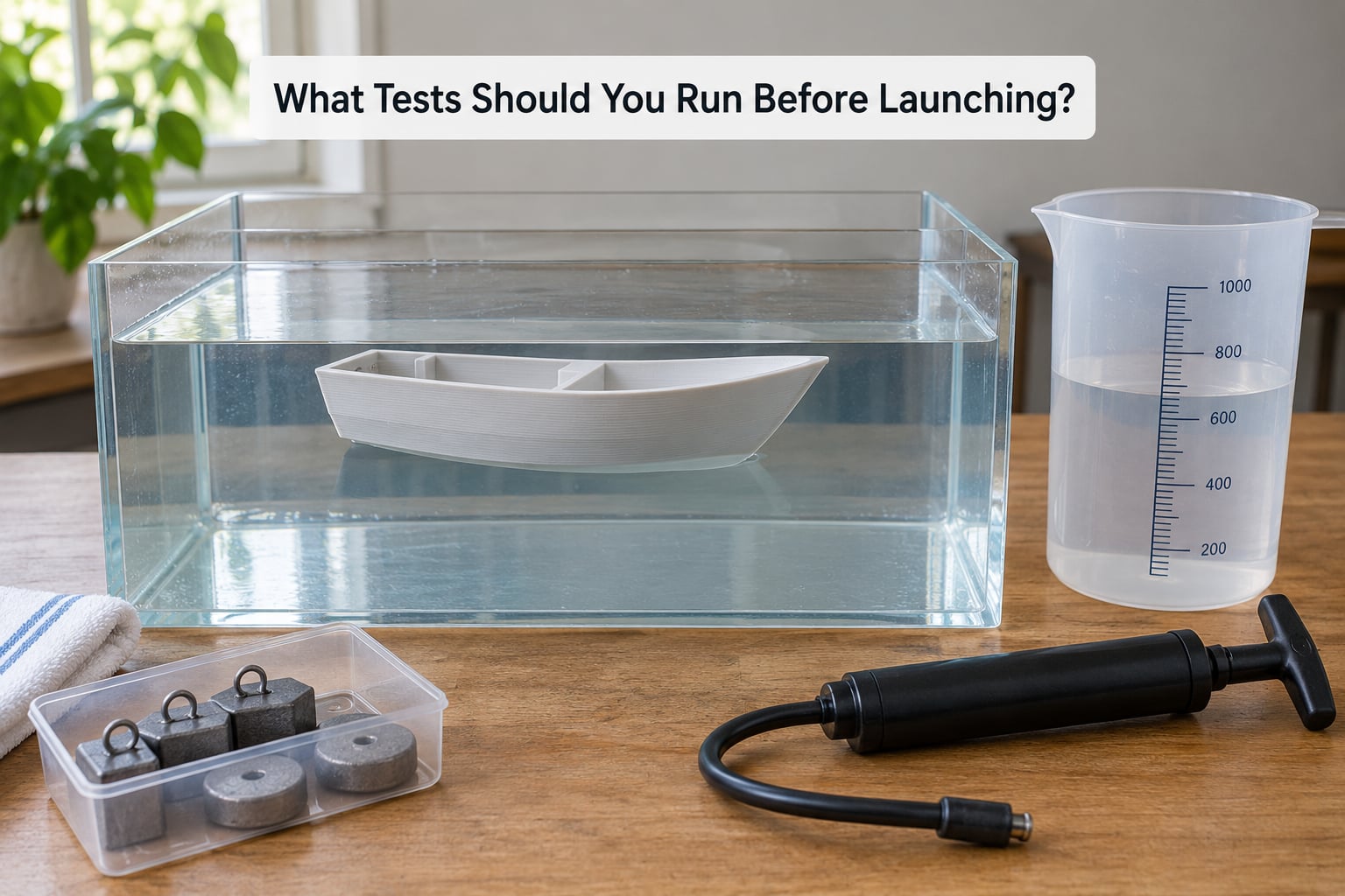
Testing is not a formality, it is the part that tells you whether the last sixty hours of printing were worth it. Run it in stages, and do not skip ahead because you are impatient. A tank, a graduated container and a set of small weights will tell you more than a launch will.
The staged test plan
- Dimensional check. Measure the beam, the draft and the freeboard against your design numbers before anything else. If the print came out warped, the loading calculations downstream are meaningless.
- Water-tightness test. Fill the sealed hull and leave it, then check it again after a few hours and overnight. Mark every seep and fix it before moving on.
- Load test. Add ballast in stages to your calculated total mass and watch the freeboard. If the boat sits deeper than you expected, find out why now, not on open water.
- Displacement check. Float the hull in a tank and measure how much water it pushes aside. Compare the measured litres against your calculation; this is the cheapest buoyancy validation available.
- Stability and trim. Load the real battery and electronics, then check that the boat floats level and recovers from a heel rather than rolling.
- Motor and electronics test in a bucket or tub. Run the drive, steering and any autopilot with the hull restrained. Water ingress at the shaft seal or connector is far cheaper to find here.
- Sheltered first launch. Start in a calm, shallow, familiar spot with a throw line attached and someone on the bank. Add load gradually and keep the electronics in a dry bag until you trust the seals.
Keep a log of the masses, the freeboard readings and the weather for each run. It is the only way to answer the question you will ask later, which is whether a change to the hull, the coating or the load actually helped.
Where Do 3D Printed Hulls Make Sense?
Printed hulls earn their place where the mould is the problem, not where the laminate is. No tooling means a one-off shape is affordable, and a parametric model means the second boat is a file change rather than a new set of patterns. That is why the real projects cluster in a few specific places.
Where it works well
Model and RC boats are the strongest case, and the community has already settled most of the questions. Kayaks, paddle craft and small rowing skiffs work because the loads are modest and the hull is a shell, not a structure. Unmanned surface vessels are a natural fit, since the hull can integrate sensor mounts, cable ducts and antenna housings in one piece instead of bolting them on. Marine spare parts, jigs, sacrificial forms and mould tools are arguably the highest-value use, because a broken fitting on a working boat is expensive to replace quickly and cheap to print. Full-scale demonstrators matter too, as a printed hull is a credible way to prove a hull form before anyone cuts a mould.
Large-format systems have been doing exactly this at real scale. The 3Dirigo, printed at the University of Maine in 2017, and the rpDock floating dock printed in 2018, were followed by Sea Relativity’s printed vessels, the 12 m Faber Navalis hull from CEAD and the University of Maine, and Voltage Vessels’ Eclipse X9 composite RHIB prototype. Several of these teams state plainly that certification was not the goal. They are demonstrators, and reading them as proof that certified service hulls can be printed overreads the evidence.
Where it does not
Anything with people aboard who depend on the hull in a serious sea state, anything that has to meet a class or flag requirement, and anything where a failure ends in injury rather than a lost afternoon. Cold moulding, CNC-cut frames and lofted jigs, glass over a printed form, and conventional GRP or aluminium remain better choices. On the BoatDesign.net thread, senior builders make this argument without much sentiment: the technique is not competitive for large parts, and a printed plastic hull is the wrong answer to a strength problem.
The sensible middle path for a serious builder is to print the tooling, the frames or the pattern, and let a conventional process make the hull.
Frequently Asked Questions
Can you 3D print a boat hull?
Yes, at several scales. Desktop FDM machines build model boats, kayaks and small unmanned surface vessels, and large-format systems have printed hulls up to 12 m long, including the Faber Navalis and a 6 m composite RHIB prototype. What changes with scale is everything downstream: material choice, wall thickness, post-processing and whether the result needs to be certified for service.
What material is best for a 3D printed boat hull?
PETG for small craft on a desktop machine, ASA or ABS if your printer has an enclosed heated chamber, and a glass or basalt fibre reinforced thermoplastic for large-format work. Avoid PLA outdoors. The best published marine data comes from fibre-reinforced PETG tested at about 108 MPa tensile, retaining over 90 percent of that strength after long-term salt water immersion.
Is FDM output watertight on its own?
Do not rely on it. A printed hull is a solid perimeter over a lattice of channels, and those channels only close if every layer bonds to the one below. Many builders seal a model hull with a coat of paint, but for anything you row or power, sand the surface, fill the print lines and seams with polyester filler, then coat with epoxy or a marine coating, and test it filled with water before adding hardware.
What wall thickness should a 3D printed hull be?
For model and RC hulls, 1.2 to 1.6 mm of wall is normal. For a hull you will row, power or launch, go to 2 to 4 mm and use three or four perimeters. Wall thickness is the strongest lever you have on both strength and print time, so it is worth raising before you add infill. Ribs, a keel and a stringer along the load path add more strength per hour of print than a higher infill percentage.
How does 3D printing change a boat’s buoyancy?
A printed shell has less displacement than a moulded hull of the same shape, but it is also much lighter, so it floats higher rather than sitting dangerously low. Measure both sides of the equation: weigh the finished hull and coating, add the mass of the motor, battery, electronics and ballast, then float the hull in a tank and check that the litres it displaces match your calculation. Keep a quarter of the displacement in reserve.
Are 3D printed boats seaworthy and legal?
It depends entirely on the job. A printed kayak, a USV hull or a model boat is a legitimate build. A passenger-carrying or commercial-service hull is a different matter, because most flag and classification authorities expect a documented structural test, a defined laminate schedule and traceability, none of which additive manufacturing currently provides routinely. Several large-format teams have said outright that certification was not the goal of their prototypes.
Conclusion: Start With a Small, Testable Hull
Most printed hull projects go wrong in the same place, which is starting too big. Pick the smallest hull that teaches you the thing you do not know yet, on a machine you can print a test section on tonight.
Choose a water-resistant material for the exposure your hull will actually see. Design the section around the 45 degree overhang limit so the print supports itself. Seal the seams properly rather than hoping the print is watertight. Calculate your load and keep a margin. Then work through the staged tests in a tank before you put a motor in it or go near open water.
Once that hull floats, trims and survives a day on the water, scale the file and keep everything else the same.