To ground a small boat electrical system, you run one heavy tinned copper cable from the battery negative to a ground bus bar, land every accessory negative on that bar, and leave the hull out of the DC return path entirely. On a 16 to 25 foot skiff or center console the whole job is one bus bar and maybe a dozen terminations, and it takes an afternoon with a multimeter and a crimp tool.
The reason this matters is that most small boats with flaky electronics do not have an electronics fault. They have a loose, corroded or undersized ground lug somewhere in the loom, and the symptom shows up as flickering nav lights, a chartplotter that reboots every time the starter turns, or a zinc anode that eats itself in a few months.
What follows is the same sequence I would walk through on my own boat: identify what is actually on the hull, plan the return path back to the battery, land it on a real bus bar, protect it, then verify with numbers. There is a lot of confusion in the forums about grounding versus bonding, so that distinction gets its own section before we touch a wire.
Table of Contents
- What You Need
- Step-by-Step
- Step 1: Identify the Boat’s Electrical Arrangement
- Step 2: Consult the Wiring Diagram and Manufacturer Instructions
- Step 3: Disconnect Power and Prevent Accidental Startup
- Step 4: Inspect Metal Hull and Hull Connections
- Step 5: Ground a Small Boat Electrical System Without Using the Hull
- Step 6: Add Fuses, Breakers and Overcurrent Protection
- Step 7: Protect Cables Against Moisture and Chafe
- Step 8: Test the Installation Before Re-energizing
- Common Mistakes
- Frequently Asked Questions
What You Need
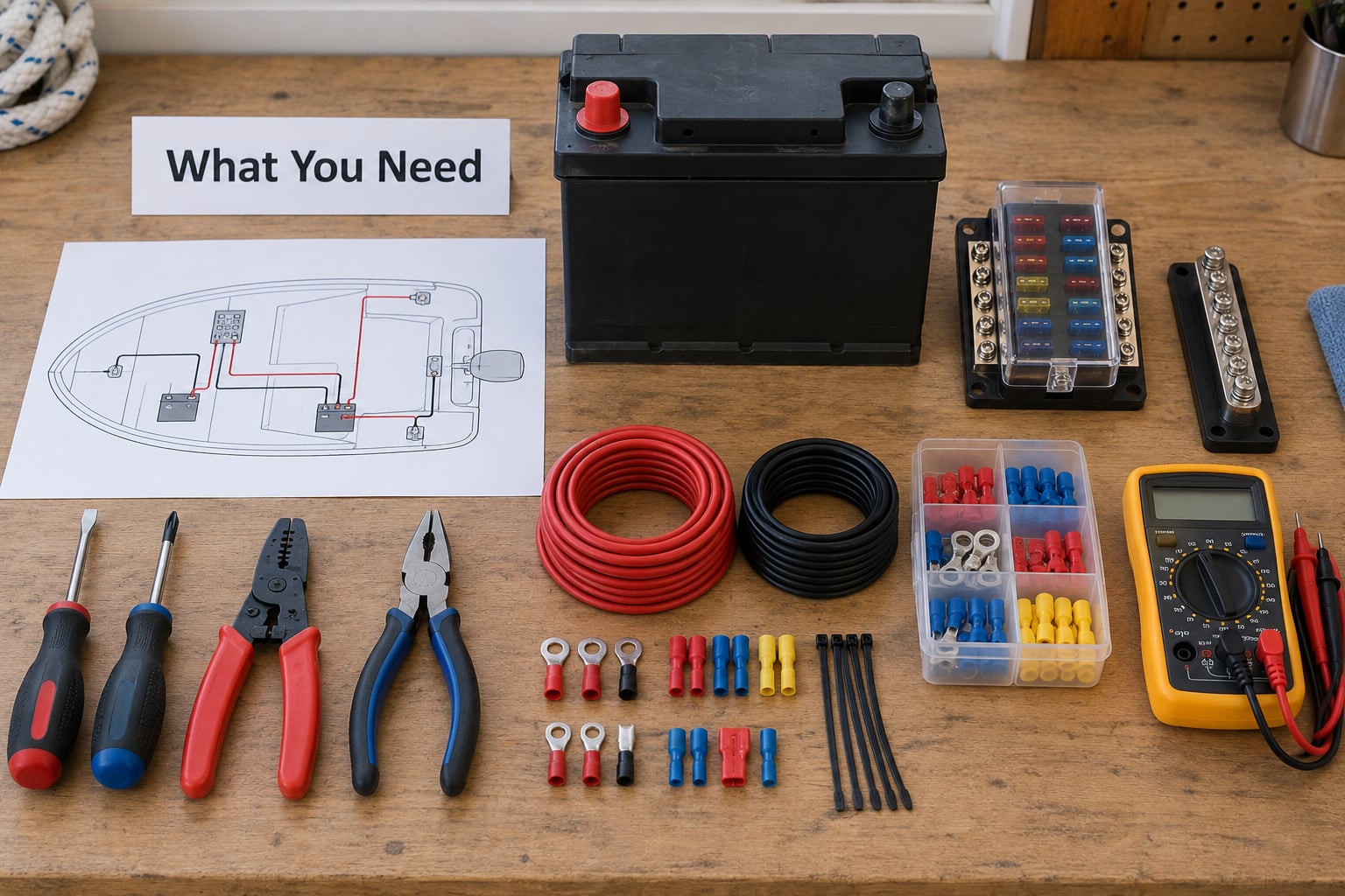
The correct grounding system depends on what your boat actually has. A jon boat with a trolling motor, a pair of batteries and a fish finder needs one bus bar. A 24 foot center console with a dual battery bank, an inverter, a solar controller and shore power needs considerably more. Before you buy a single lug, inventory your electrical arrangement so the ground design matches it.
Tools
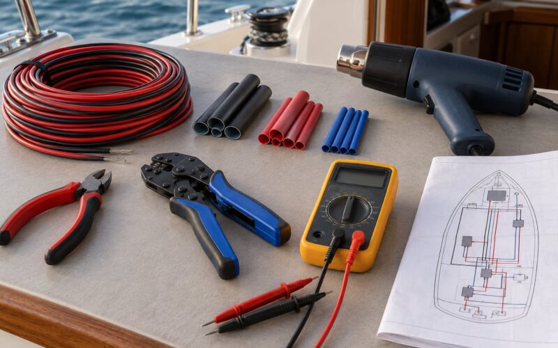
- A digital multimeter, plus a clamp meter for leakage and load checks
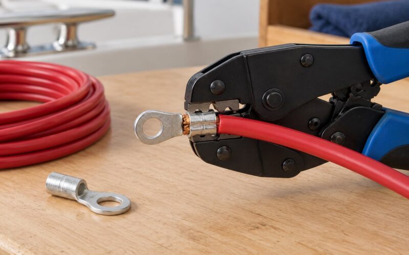
- A quality ratcheting crimper with marine-grade tinned copper terminals
- Wire strippers, ring terminal crimper, heat-shrink gun and adhesive-lined heat shrink tubing
- Wire size chart or an ABYC sizing table, and a ring terminal for every stud you plan to use
- A wire ferrule crimper, used to crimp the main battery-to-bus cable before the lug goes on
- Torque driver for bus bar studs, plus a backup wrench and a locking compound that resists vibration
- Battery terminal protector or grease, non-corrosive and non-hardening
- Fish tape, cable ties, loom and spiral wrap for the finished run
Components
- Stranded tinned copper marine-grade wire in marine insulation, not automotive wire from a hardware store
- A ground bus bar with enough studs for every returning circuit plus two or three spares
- Ring terminals matched to each bus bar stud, one conductor per stud where the current justifies it
- A main negative cable from the battery, and a short engine-to-battery negative jumper if the boat has an outboard or inboard
- Marine-rated fuses or breakers for every circuit leaving the bus
- A bonding jumper for each piece of underwater metal you intend to bond: through-hulls, prop shaft, rudder post, engine
Safety gear and documentation
Get eye protection, insulated tools and gloves rated for battery work. Have a pair of terminal lugs that fit your battery posts, since lead-acid batteries shed a corrosive mist and sparks near them are worth avoiding. Also pull the wiring diagram if the boat came with one, plus the manuals for the charger, inverter, solar controller and any accessory you plan to add. On an older boat with no diagram, treat whatever you find as unknown until tested.
Access matters too. You need room to reach the bus bar with a wrench, a dry place to work, and lighting that reaches inside the console. A ground bar crammed behind a battery you cannot get a wrench to will be a problem at exactly the wrong moment.
Step-by-Step
Step 1: Identify the Boat’s Electrical Arrangement
Map every electrical item on the boat before you decide on a layout. Start at the batteries and count them, then trace the battery selector switch and any isolator. Note the engine and whether a negative jumper already runs from the engine block to a battery post.
Next, list every load: nav and anchor lights, deck lights, bilge pump, high-water alarm, livewell pump, console electronics, fish finder, chartplotter, VHF radio, autopilot, horn, USB outlets, trailer winch, trolling motor, and any solar controller or inverter. Write down the fuse or breaker size for each one, because that number drives your ground conductor size later.
Finally, note shore power, a generator or an inverter, and every piece of metal that touches the water: through-hulls, the prop shaft, rudder and prop, trim tabs, and the engine. Metal hulls, aluminum transoms and wood or fiberglass construction each change which surfaces you can use, and that mapping decides the whole plan.
Step 2: Consult the Wiring Diagram and Manufacturer Instructions
Read the wiring diagram that came with the boat, or the one from the builder, and compare it to what you mapped in Step 1. Diagrams drift out of date, so treat the boat as the source of truth and the paper as a guide.
Read the accessory instructions too. Nearly every fish finder, VHF and stereo says something like ground to the boat’s common ground, and nowhere does it say where that physically is. The answer on almost every small boat is the ground bus bar, and this guide is where you find it. If the manufacturer’s instructions call for a connection somewhere you did not anticipate, follow their direction and tell your marine electrician about the conflict.
This is also the point to decide whether the job needs a professional. An ABYC-certified technician should review the plan first when you are adding shore power, an inverter, a generator or a second battery bank, or when the boat has aluminum construction, a wood hull with a metal liner, or no wiring diagram at all.
Step 3: Disconnect Power and Prevent Accidental Startup
Isolate every source before you cut anything. Switch off the battery selector, remove the negative cable from the battery first, then the positive. Pull the fuses or open the main breaker on each circuit you intend to work near.
Deal with solar and inverter inputs too. A solar controller can keep a panel array live in daylight even with the battery disconnected, so cover the panels or disconnect the panel side at the controller. If the boat has a generator or an inverter charger, shut it down at its source and confirm it will not start back up on its own.
Label everything as you go. Fusing is the last line of defense against a mistake, not the first, so treat the disconnected battery as the primary control. Work with eye protection on, and keep metal tools from bridging across a battery post.
Step 4: Inspect Metal Hull and Hull Connections
Now look at what you are working with. Scrape corrosion off connection points down to bright metal, check for paint and sealant at each candidate surface, and look for cracks or movement around through-hull fittings and shaft logs. A ground lug bolted onto a surface with paint under it is not a connection, it is a slow leak.
Rank the surfaces honestly. This is the question that comes up most often in owner forums, and the answer is narrower than people expect.
| Surface | Can it take a ground lug? | Notes |
|---|---|---|
| Dedicated ground bus bar bolted to a solid backing | Yes | The primary DC ground point on most small boats. Mount it low, dry and reachable. |
| Battery negative post or a battery terminal strip | Yes | Origin of the DC return. Protect it with a boot and terminal grease. |
| Engine block with an existing negative jumper | Yes, as a reference | Common on boats with an outboard or inboard. The jumper makes the block part of the negative network. |
| Bare metal hull, keel bolt or metal liner on a wood hull | With care | Clean to bright metal, seal the exposed area, and use a dedicated bonding or grounding plate. |
| Aluminum transom or outboard drive | Yes for bonding, isolated for ground | Bond to the system, but keep DC negative off the transom unless the builder specifies it. |
| Painted, sealed or anodized surface | No, not bare | Scrape to metal and use a dedicated plate rather than drilling the finish. |
| Fiberglass hull, no liner | No | Use a purpose-built ground lug with a backing block, bolted through from inside. |
| Mast, handrail, pulpit or lightning rod | No | Those are lightning conductors, not DC grounds. They carry strike current, not return current. |
Two things on that table deserve emphasis. First, the mast and rails are lightning protection hardware, and the lightning ground bolt is a separate system from your electrical ground even though both end up in the water. Second, fiberglass is not a dead end. A bolted-through ground lug with a backing block on the inside of the hull gives you a solid attachment point, and that is the standard answer for a fiberglass boat with no metal hull to bond to.
Step 5: Ground a Small Boat Electrical System Without Using the Hull
This is the step people get wrong, so state the rule plainly: on a DC system, every negative returns to the battery negative and nothing else. Not the hull, not the bonding system, not a through-hull, not the engine block as a separate path. Build the boat’s electrical system as if the hull were rubber-mounted, the same way a car sits on rubber tires, and the DC side is insulated from the vessel itself.
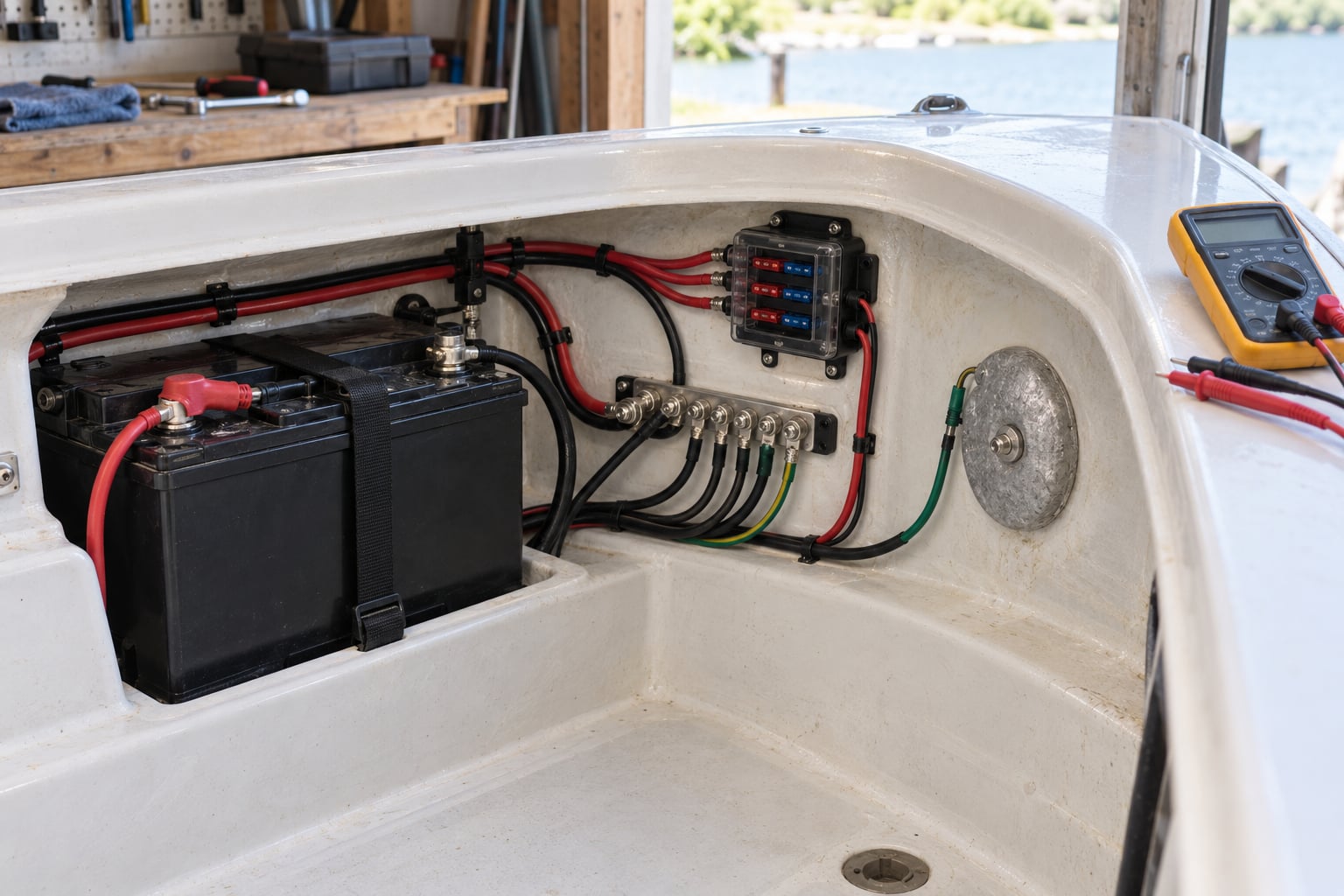
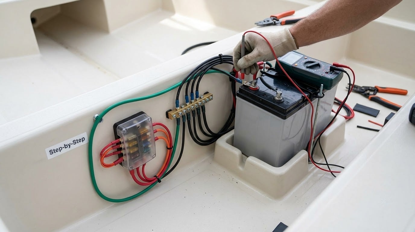
Start at the battery. Crimp a ferrule onto the main negative cable, then a ring terminal that fits the post, and fit a protective boot. Run that cable to the ground bus bar and land it on its own stud. On a boat with an engine, run a heavy jumper from the engine block to the same battery negative so the starter and alternator share the negative network properly.
Mount the bus bar on a backing plate in a dry, ventilated, reachable spot, with the studs that will carry real current torqued per the manufacturer’s spec. Then land each accessory negative on its own stud with a properly sized ring terminal.
Give each high-current device its own stud rather than doubling up with a second wire under one lug. Doubling lugs into a single stud is common in DIY work and it is a weak point, because two undercrimped lugs make poor contact on a vibrating boat. If a stud needs two circuits, split it with a proper bus bar block or two studs joined by a short jumper.
Seal every connection with adhesive-lined heat shrink and keep the corrosion off with terminal grease. A bus bar mounted inside a damp console with bare copper will be a corroded bus bar within a season.
Step 6: Add Fuses, Breakers and Overcurrent Protection
Circuit protection sits in the positive feed, not in the ground. Every circuit needs a marine-rated fuse or breaker sized to the wire, sized to the load, and located close to the source so the wire between the source and the device is protected.
Size the conductors to the load and the run length together. Longer runs need heavier wire to hold voltage up under load, and a ground conductor that is undersized shows up as mysterious resets under exactly the conditions you care about, like starting the engine with electronics running.
| Load | Typical draw | Fuse or breaker | Wire size for a typical run |
|---|---|---|---|
| Navigation and anchor lights | 2 to 4 A | 5 to 10 A | 16 AWG |
| Livewell or deck wash pump | 5 to 8 A | 10 A | 14 AWG |
| Console electronics, VHF, autopilot | 3 to 10 A | 10 to 15 A | 14 AWG |
| Bilge pump and high-water alarm | 10 to 15 A | 15 to 20 A | 12 AWG |
| Trolling motor, up to about 30 A | 30 A | 30 A | 10 AWG, run as short as possible |
| Inverter or battery charger | 30 to 50 A | 40 to 60 A | 6 AWG, shorter for a 50 A charger |
| Engine starting | 150 to 250 A | Not fused, cable-mounted | 4 to 2 AWG battery cable |
| Battery to ground bus bar | Main feed | Protected at the battery | 8 AWG or heavier for a small boat |
Use marine-grade stranded tinned copper. Automotive wire from a hardware store is the wrong insulation for a wet, salty, hot compartment, and it is a common shortcut on cheap boat installs. Crimped terminals beat soldered ones on a boat because the joint stays slightly flexible and vibration cannot crack a solder bead the way it can fatigue metal lugs.
One warning: a grounding conductor is not a protective device. Running a thin wire from a device to the ground bus does nothing to interrupt a short, and it is no substitute for a correctly sized fuse in the positive lead.
Step 7: Protect Cables Against Moisture and Chafe
The most common failure on any boat is not a bad part, it is a wire that rubbed through on a sharp edge. Route ground cables away from sharp edges, moving steering, propeller and shift hardware, and anything that gets hot. Support cables along their length with loom, fish tape or P-clamps every foot or so, so weight does not swing them against a bulkhead.
Add strain relief at both ends. A ground lug that carries the full weight of a cable will slowly work loose, and a loose ground lug is the exact symptom you set out to prevent.
At every penetration through a bulkhead, deck or hull, seal it and fit a grommet or chafe sleeve. Where a cable enters below the deck line, leave a drip loop so salt-laden water runs off instead of running along the cable into the connector. Use corrosion-resistant hardware and locking compounds that hold up under vibration, and keep ground connections above the deck where practical.
Step 8: Test the Installation Before Re-energizing
Before reconnecting anything, check your work cold. Confirm each accessory’s negative lands on the ground bus, each positive has its own fuse or breaker, and no ground connection has crept onto the hull.
Measure resistance from each equipment ground lug to the battery negative terminal with everything disconnected. Close to zero ohms on every path, with no surprises such as a low-resistance path to the hull. Then reconnect the battery and work through these readings.
| Measurement | Where | Expected reading |
|---|---|---|
| Resting battery voltage | Across battery posts, loads off | About 12.6 V for a fully charged 12 V battery |
| Voltage drop under load | Battery negative to the equipment ground lug, load running | Under 3 percent for sensitive electronics |
| Neutral to ground | AC system, if the boat has shore power | Near 0 V on the boat side of the source |
| Leakage current | Clamp meter on the AC feed, normal conditions | Close to zero |
| Ground continuity | Bonding jumper to hull metal | Near 0 ohms |
| Engine block to battery negative | Engine off, jumper installed | Near 0 ohms |
Voltage drop is the number that catches most problems. Measure it while the load runs: put one meter lead on the equipment ground lug and the other on the battery negative, with the other lead of the meter pair across the positive feed. Anything approaching 10 percent points at a corroded lug or a conductor that is too light for the run.
If you own a clamp meter, check for leakage current with the boat switched to shore power. Small amounts of leakage show up as anodes that vanish in a season. Do not do live AC measurements beyond what your meter is rated for, and stop at once if a result is unclear or a reading is outside what the meter should see.
Common Mistakes
Almost every ground fault I have chased came from one of these, and they run in order of how much damage they cause.
- Grounding DC negative to the hull or the bonding system. This is the big one, and it is the mistake experienced owners keep warning newcomers about in sailing and small-craft forums. It puts the hull into the DC return path, drives stray current into the water and eats prop shafts and through-hulls. The fix is to remove that connection and route the negative back to the battery negative and the bus bar only.
- Using automotive wire. Cheap insulation, no stranding to suit a vibration environment, and no marine-grade temperature rating. Replace it with stranded tinned copper in marine insulation.
- Attaching grounds to whatever metal is nearby. A rail, a cleat, a bracket or a painted surface is not a ground point. Use the bus bar, a dedicated lug with a backing block, or a clean metal surface the builder designated.
- Painting over the connection, or sealing it before it is clean. A lug under a coat of paint or sealant is a resistance that gets worse. Scrape to bright metal, make the connection, then protect the bare metal around it.
- Leaving circuits unfused, or fusing after the run. The fuse belongs close to the source, sized to the wire. A fuse at the far end of a long unprotected run protects almost nothing.
- Undersized conductors. Especially ground conductors on electronics circuits and long runs. Thin wire behaves like a heater under load, drops voltage, and fails at the terminal first.
- Ignoring aluminum hulls or transoms. Aluminum and the engine hardware need deliberate bonding with an isolation strategy, not a random bolt. Aluminum needs its own hardware and a sealant that isolates dissimilar metals.
- Bypassing the shore-power galvanic isolator or bonding neutral and ground onboard. AC neutral and AC ground must stay separate on the boat and be bonded only at the source, whether that source is the pedestal, a generator or an inverter. Bonding them onboard creates a path for galvanic current and defeats the isolator.
- Confusing the lightning ground with the electrical ground. A lightning ground bolt on the mast carries strike current into the hull. It is not a DC return path and should not be used as one.
A few habits keep the system working. Recheck and re-torque bus bar connections once after the first month of vibration, then annually with the rest of the boat. When a breaker or fuse trips, find out why instead of resetting it. Keep terminal grease on battery posts and bus connections, and pull the anodes on schedule, because a zinc that disappears in two months is telling you there is stray current in the system.
Two symptoms deserve an immediate look: flickering nav lights that change brightness when the engine is running, and electronics that reset when the starter engages. Both point to a shared ground that cannot carry the load. And if you are adding shore power, an inverter or a generator to a boat that never had it, stop and have an ABYC-certified marine electrician design that part first.
Frequently Asked Questions
Does a small boat electrical system need a ground?
Yes. A small boat DC system needs a defined return path back to the battery negative so current flows through wire rather than through the boat. Every accessory negative lands on a ground bus bar, which ties to the battery negative. Boats with AC systems need a green ground conductor as well, bonded at the power source. Without a proper ground, stray current attacks underwater metals and electronics get intermittent resets.
Is boat grounding the same as bonding?
No, and the difference matters. Grounding is a safety path that carries fault current back to its source so a breaker trips. Bonding joins metal pieces so they sit at the same voltage, limiting touch voltage and stopping galvanic corrosion of underwater metals. On a DC boat, the negative runs to the battery only, and the hull bonding system handles the underwater metals separately. The two systems meet only where ABYC specifies.
What size ground wire should I use on a small boat?
For most skiffs, jons and center consoles under about 25 feet, 8 AWG stranded tinned copper from the battery negative to the ground bus bar is the common starting point. Each accessory then gets a ground conductor sized to its own load and run length: 14 AWG for electronics, 12 AWG for a bilge pump, and heavier for chargers and inverters. Longer runs and higher currents need heavier wire to hold voltage drop down.
Does shore power require a galvanic isolator?
A galvanic isolator is not strictly required everywhere, but it is the accepted fix for accelerated zinc and prop corrosion caused by DC current from a dock. It blocks the DC path while leaving AC power flowing. Most small boats plug in without one and quietly lose anodes. A monitor or isolation transformer is an alternative, and any of these must never be built by bonding neutral and ground onboard.
Can I ground the system to the engine block?
The engine block is part of the DC negative network when a heavy jumper runs from it to a battery negative, which is normal on many boats. What you should not do is use the engine block as the only ground path, or land accessory negatives on it instead of a bus bar. It is a convenient reference point for measuring, not a general purpose ground terminal, and it should never be bonded to the hull for DC return.
When should I hire a marine electrician?
Hire an ABYC-certified technician whenever you are adding shore power, an inverter, a generator or a second battery bank, when the boat is aluminum or has a wood hull with a metal liner, or when no wiring diagram exists. It is also worth it if AC measurements are outside your comfort, if a breaker keeps tripping, or if the corrosion rate on your anodes is clearly wrong. The DC bus on a small boat is usually a reasonable weekend job; the AC side is not.
Start with the mapping in Step 1, then the bus bar and the single heavy negative cable back to the battery. That one afternoon of planning is what separates a system that stays quiet for years from one that leaves you chasing flickering lights on every trip.