If you want to know how to crimp marine wire properly, the short answer is this: a good marine crimp is a cold-formed, mechanical connection made by squeezing a tinned-copper terminal onto stranded tinned-copper wire with a matched ratcheting crimper, then sealing it with adhesive-lined heat shrink. No solder, no twisting, no wire nuts. Get those four things right and the joint resists salt air, vibration and flex for years. Updated for 2026.
Most boat electrical trouble starts at a connection that got loose or corroded. Added resistance turns into heat, heat into a failed component or a fire, and low-voltage DC faults sit near the top of the causes listed in annual marine casualty reporting. ABYC goes further and names solder as an unacceptable sole mechanical connection in E-11.16.3.7, which tells you how seriously the standards bodies take this joint.
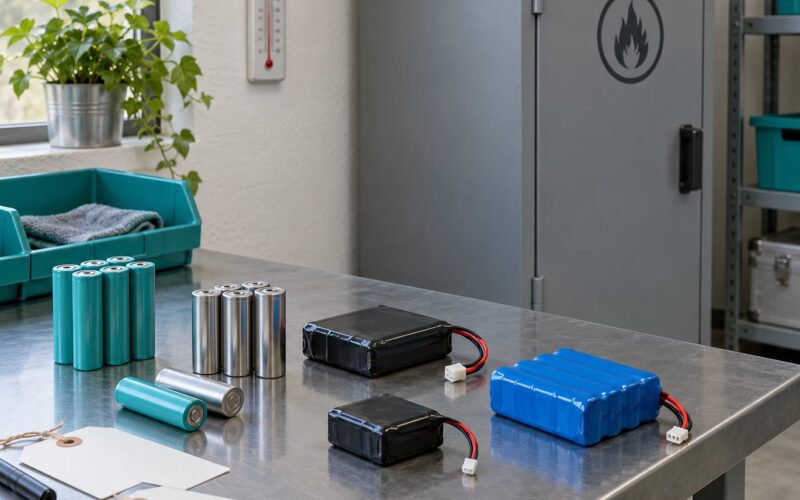
The same discipline applies off the boat. Anyone building low-voltage sensor harnesses, underwater instrument pods or small ocean robots hits the same barrel, die and seal questions, usually in a damp enclosure where a marginal joint shows up as a sensor that drops out for no reason.
Table of Contents
- What You Need
- Step-by-Step: How to Crimp Marine Wire Properly
- Frequently Asked Questions
- Can I use ordinary automotive wire instead of marine wire?
- Do I need tinned copper wire for a marine crimp connection?
- What type of terminal is best for marine wire?
- Is adhesive-lined heat-shrink tubing necessary on marine connections?
- Should I solder a wire after crimping the terminal?
- How can I tell whether a crimp connection is loose?
- Conclusion
What You Need
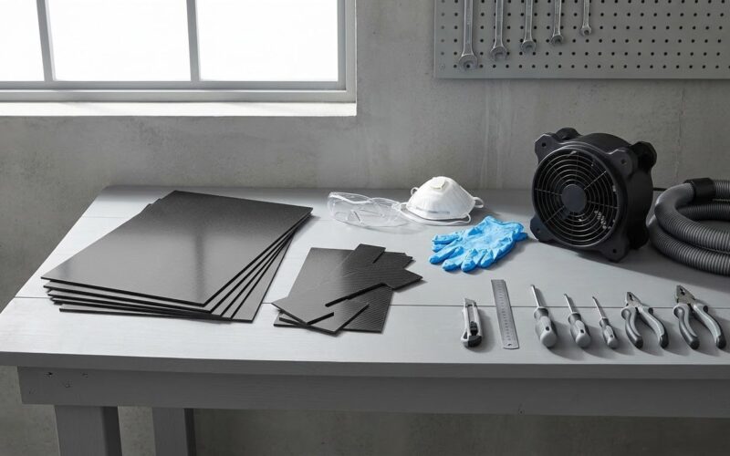
Six items cover almost every marine crimp: the correct conductor, the right terminal or lug, a ratcheting crimper, a proper stripper, adhesive-lined heat shrink tubing, and the circuit documentation that tells you what you are actually building.
The wire. Marine wire is stranded, tinned copper, typically rated to 105°C and built to UL 1426. Tinning the strands slows corrosion, which is why it matters in salt air and in bilge water. Automotive wire works in a dry cabin; it does not belong in an engine room or a through-hull run.
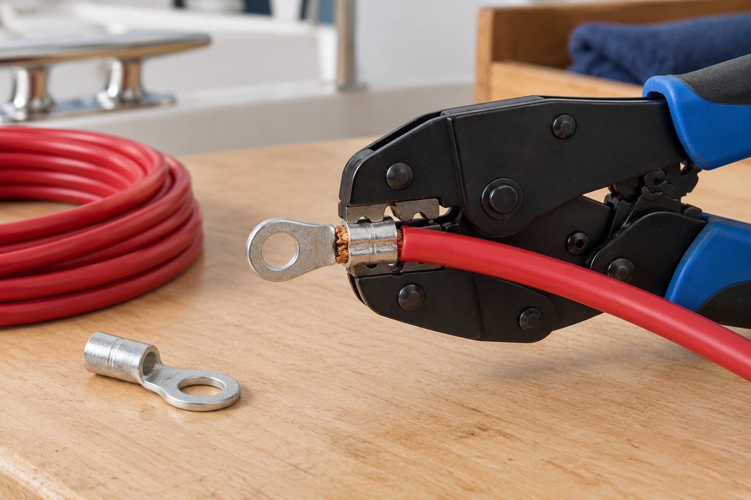
The terminal or lug. Barrel size must match conductor size. An oversized barrel leaves loose strands that never deform; an undersized barrel crushes the wire and splits the insulation. Match the manufacturer size chart to the wire you actually have in hand.
A ratcheting crimper. Not the strip-crimp pliers from the drawer. A controlled-cycle crimper has a matched, colour-coded die nest, parallel-moving jaws, and a ratchet that will not release until the cycle finishes. That ratchet is the whole point: it prevents under-crimping, which is the single most common failure.
A stripper. A manual or automatic stripper that cuts the jacket without nicking strands. Your thumbnail is not a stripper.
Adhesive-lined heat shrink tubing sized to the finished joint, plus a heat gun. Never an open flame, and never heat shrink anywhere near a fuel vapour, propane or diesel component.
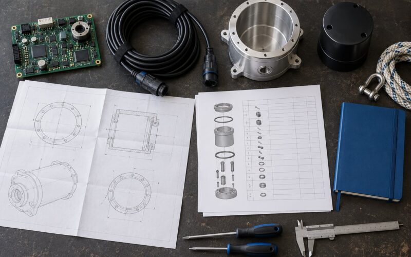
The drawings. Battery, controller, fuse block and boat wiring diagrams. Before you cut anything, confirm what the circuit carries, what size conductor it needs, and what protection it depends on.
| Wire size | Die colour | Typical terminal | Strip length |
|---|---|---|---|
| 22-18 AWG | Red | Red PIDG or heat shrink butt | about 1/8 inch, per terminal instructions |
| 16-14 AWG | Blue | Blue PIDG or heat shrink butt | about 1/4 inch |
| 12-10 AWG | Yellow | Yellow PIDG or ring terminal | about 5/16 inch |
| 8-6 AWG | Red, larger nest | Heat shrink ring terminal | about 3/8 inch |
Treat that strip column as a starting point, not gospel. Open-barrel and insulation-displacement terminals want different depths than closed-barrel ones, and the terminal instruction sheet wins over any chart on the internet.
Safety first: identify the circuit, then disconnect power at the source and confirm it is dead. Remove stored energy where the equipment holds any, and work to the boat or equipment manufacturer’s specifications. Electrical work on a boat is regulated in places, and mains-side work belongs to a licensed electrician.
Step-by-Step: How to Crimp Marine Wire Properly
The core procedure in six moves: cut square, strip to the marked depth, slide on the heat shrink before you crimp, insert to full depth, squeeze until the ratchet releases, and tug to confirm. Each stage has a check. Skip the check and you find out later with a voltage drop.
Step 1: Verify the Circuit and Connection Requirements
Trace the circuit from the load back to its source. Confirm the load current, the required conductor size, and the polarity, because a reversed cable in a DC system is a very expensive mistake to discover at the switch.
Open the relevant fuse or breaker, disconnect the battery negative if the manufacturer’s procedure calls for it, and verify there is no voltage at the work point. Then check the wiring diagram for what the circuit needs: conductor size, fusing, terminal type, and any rating the controller or battery requires.
Success check: you can state the load, the wire size, the polarity and the protection for this circuit without guessing.
Step 2: Cut, Strip, and Prepare the Conductor
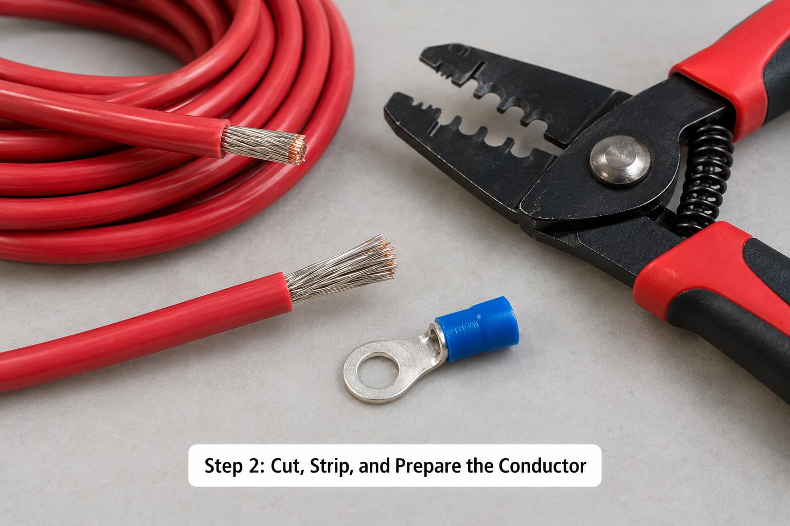
Cut the conductor square with proper cutters. A crooked cut makes the strands fan out at the entry of the barrel.
Set the stripper to the length the terminal instructions call for, typically the marked depth on the terminal itself. Strip only that much. Longer strips leave bare conductor exposed past the barrel, which is exactly where corrosion starts.
Do not twist the strands. Do not fray them. Do not nick the conductor or cut into the insulation: every nicked strand is a strand that carries less current and breaks sooner. If the strip comes out rough, change the stripper blades or the blade depth rather than trying again until you get lucky.
Tinned copper strands should look silver-grey and stay together as a bundle. Bare copper is usable inside a sealed, dry enclosure but is a poor choice anywhere salt reaches it, and aluminium conductor is a separate wiring system with its own terminals and inhibitor.
Success check: the strands are intact and parallel, the conductor is clean, and no copper sits exposed beyond the length the terminal expects.
Step 3: Insert the Wire and Form the Crimp
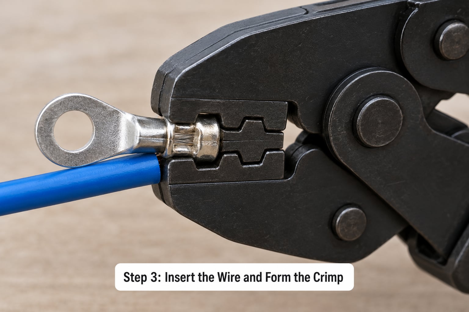
Slide the heat shrink tubing on before you crimp. Once the terminal is on the wire, it will not slide on backwards, so this is the only chance.
Insert the conductor until the insulation seats against the barrel’s shoulder and the strands fill the barrel with no daylight at the end. Every strand needs to be inside the barrel. One stray strand folded back under itself is a permanent weak point.
Set the crimper to the die nest matching your gauge, place the terminal in the nest with the wire end toward the strain-relief side, and close the handles slowly until the ratchet releases. Squeeze hard and steady; the sound you want is the tool finishing its cycle, not your muscles finishing theirs. A crimp should leave the barrel visibly indented and symmetrical, with no cracks running down the side.
Terminals come in three flavours, and they are not interchangeable. Open-barrel terminals are for fine-stranded wire and open-barrel dies. Closed-barrel terminals wrap fully and suit heavier conductors. Insulation-displacement or PIDG terminals use a second crimp through the insulation to add strain relief, and that second nest must be a separate, smaller die on the tool. Knock-off crimpers that use one nest for both make a double crimp inherently wrong.
Colour codes on cheap tools are not always AWG. Some are SAE or metric nests wearing the same colours. Confirm your tool’s chart against a known reference, or make a test crimp, cut it open with side cutters and look at the cross-section.
Success check: the conductor grips the terminal, no copper shows beyond the barrel, the die matched the terminal, and the joint stays secure on a firm pull.
Step 4: Add Marine Protection and Mechanical Strain Relief
Fit the adhesive-lined heat shrink over the finished joint and shrink it from the middle outward with a heat gun, moving constantly, until the adhesive melts and flows at both ends. Heat shrink seals against water, not against pressure, so it cannot rescue an interior void; shrink a bad crimp and you have sealed the failure inside a good-looking lump. Inspect before you cover.
Never use an open flame, and never run heat shrink near fuel or gas components.
For insulation-displacement terminals, crimp the strain-relief nest second, after the wire barrel, with the wire against the relief shoulder.
Route the run so the conductor is supported along its length and does not hang from the terminal. Add a drip loop where water could run along the cable, and sleeve any point where the wire crosses a sharp edge, a chafe point or a moving part. Keep butt splices and lugs inside an accessible, sealed junction box rather than behind a panel where you cannot inspect them later.
Success check: the joint is sealed, supported and not carrying the mechanical load of the cable.
Step 5: Inspect and Test the Finished Connection
Go through the joint before you close the box: conductor fully seated, crimp symmetric with no cracks, no exposed copper past the terminal, insulation undamaged, the terminal not able to rotate in the jaws of the die, and no movement at the wire.
Then pull-test it. Grab the wire close to the terminal, not the jacket further back, and pull steadily in line with the conductor. ABYC pull-test figures commonly used for acceptance are around 15 pounds for 16 AWG, 40 pounds for 10 AWG and 150 pounds for 00 AWG. Without a spring scale, a firm, deliberate tug that shows no movement or twist is the practical go/no-go check most boat owners rely on.
Measure continuity and resistance with the circuit de-energized, following the equipment’s own procedure. A crimped joint should read close to the resistance of the same length of bare conductor.
Energize in stages, watching current draw at the load and touching the connector back to your hand. A joint that gets warm faster than the wire around it has resistance in it, and you want to find that now rather than in a harbour entrance at midnight.
Common Mistakes
Almost every failed marine crimp is one of these, with a recognisable symptom.
Symptom: connection works, then warms up or fails after months. Cause: under-crimping from a tool with no ratchet, or loose strands not fully seated. Fix: recalibrate or replace the crimper, re-terminate.
Symptom: insulation splits or the barrel cracks; wire pulls out. Cause: over-crimping, usually the wrong die for the gauge. Fix: match the die to the size chart and crimp again.
Symptom: terminal rotates on the stud. Cause: barrel too small for the conductor. Fix: the right barrel, and a ring or captive spade terminal rated for the stud and the stack height.
Symptom: green or white powder on the terminal. Cause: corrosion from bare copper, wrong terminal type, or a non-marine part. Fix: cut it out, replace with a tinned marine-grade terminal, and seal it properly.
Symptom: intermittent flicker that tracks movement of the cable. Cause: no mechanical strain relief, or the conductor carrying the load. Fix: support the run, add a separate strain-relief point, relieve the terminal.
Symptom: the joint fails at a vibration-heavy location. Cause: a plier or dimple crimp with no controlled cycle. Fix: use a ratcheting crimper with the correct die, and check the routing.
Symptom: fatigue cracks after a field repair. Cause: solder added to a crimp, or solder used alone because no crimper was aboard. Solder is a repair of last resort; ABYC does not accept it as the sole mechanical connection. Fix: cut the splice out and re-terminate with a real crimp.
Symptom: repeated blown fuses after new work. Cause: a short from loose strands, or missing protection on the circuit. Fix: restore the specified fuse or breaker and re-check every termination.
Symptom: everything checks out except the test light. Cause: an unsealed joint or a bare conductor behind a panel. Fix: open it up. Most failures are visible once you look.
Before power goes back on: circuit confirmed and de-energized when stripped, correct die used, conductor fully seated with no exposed copper, crimp symmetric, pull test passed, seal shrunk, strain relief in place, and protection restored.
Frequently Asked Questions
Can I use ordinary automotive wire instead of marine wire?
Ordinary automotive wire works in a dry cabin but not where salt, damp or heat reaches it. Marine wire is stranded and tinned copper, built to UL 1426 and usually rated to 105°C, so the strands resist corrosion instead of dissolving. Keep automotive wire inside sealed, dry panels and use marine-grade wire for bilge runs, engine compartments, through-hull passes and anything exposed.
Do I need tinned copper wire for a marine crimp connection?
Tinned copper is the standard choice for exposed marine circuits. The tin coating slows the corrosion reaction that eats bare copper in salt air, and the strands stay flexible rather than work-hardening at the barrel. Bare copper is fine inside a sealed, dry enclosure. Never mix aluminium with copper in the same terminal without a designed inhibitor and bimetallic lug.
What type of terminal is best for marine wire?
For most onboard work a tinned copper ring terminal with adhesive-lined heat shrink, or a heat shrink butt connector of the matched size, does the job well. Ring terminals suit studs and keep the nut under mechanical load; butt splices join two conductors. Use insulation-displacement terminals where you want the integrated strain relief, and open-barrel lugs with fine-stranded power cable. Whatever you pick, the barrel must match the conductor.
Is adhesive-lined heat-shrink tubing necessary on marine connections?
On exposed or damp circuits it is the difference between a repair and a repeat repair. The adhesive flows into voids and bonds to both the insulation and the terminal, so water cannot sit inside the shrink. It will not fix a bad crimp, so inspect first and shrink last. Learning how to crimp marine wire properly starts with the crimper; the tubing is what keeps water out of the finished joint.
Should I solder a wire after crimping the terminal?
No. Solder on top of a mechanical crimp introduces a rigid section inside a flexible cable, and that transition point is where fatigue cracks start. ABYC does not accept solder as the sole mechanical connection, and solder wicking up the conductor can also hide an under-crimped joint. Solder is a field repair of last resort when no crimper is available, not a finishing step on a good termination.
How can I tell whether a crimp connection is loose?
Pull-test it first: grab the conductor close to the terminal and pull steadily along its axis. If it moves, twists or comes free, the crimp is bad. Warm to the touch under load also points to resistance in the joint. When a crimp pulls free, cut it open and look for voids, nicked strands or a split seam. A sound joint shears cleanly in the conductor, not at the barrel.
Conclusion
Start by confirming what the circuit needs: the load, the conductor size, the polarity and the protection, with power disconnected and verified dead. To recap how to crimp marine wire properly, that matching step comes before anything touches the conductor.
Then work the sequence without shortcuts. Match the terminal barrel to the conductor and the crimper die to the terminal. Strip only what the terminal calls for, keep the strands intact and fully seated, and close the ratcheting crimper until it releases. Confirm the joint with a pull test. Seal it with adhesive-lined heat shrink and a heat gun, add mechanical strain relief so the conductor is not carrying the load, and restore the fuse or breaker before you power up.