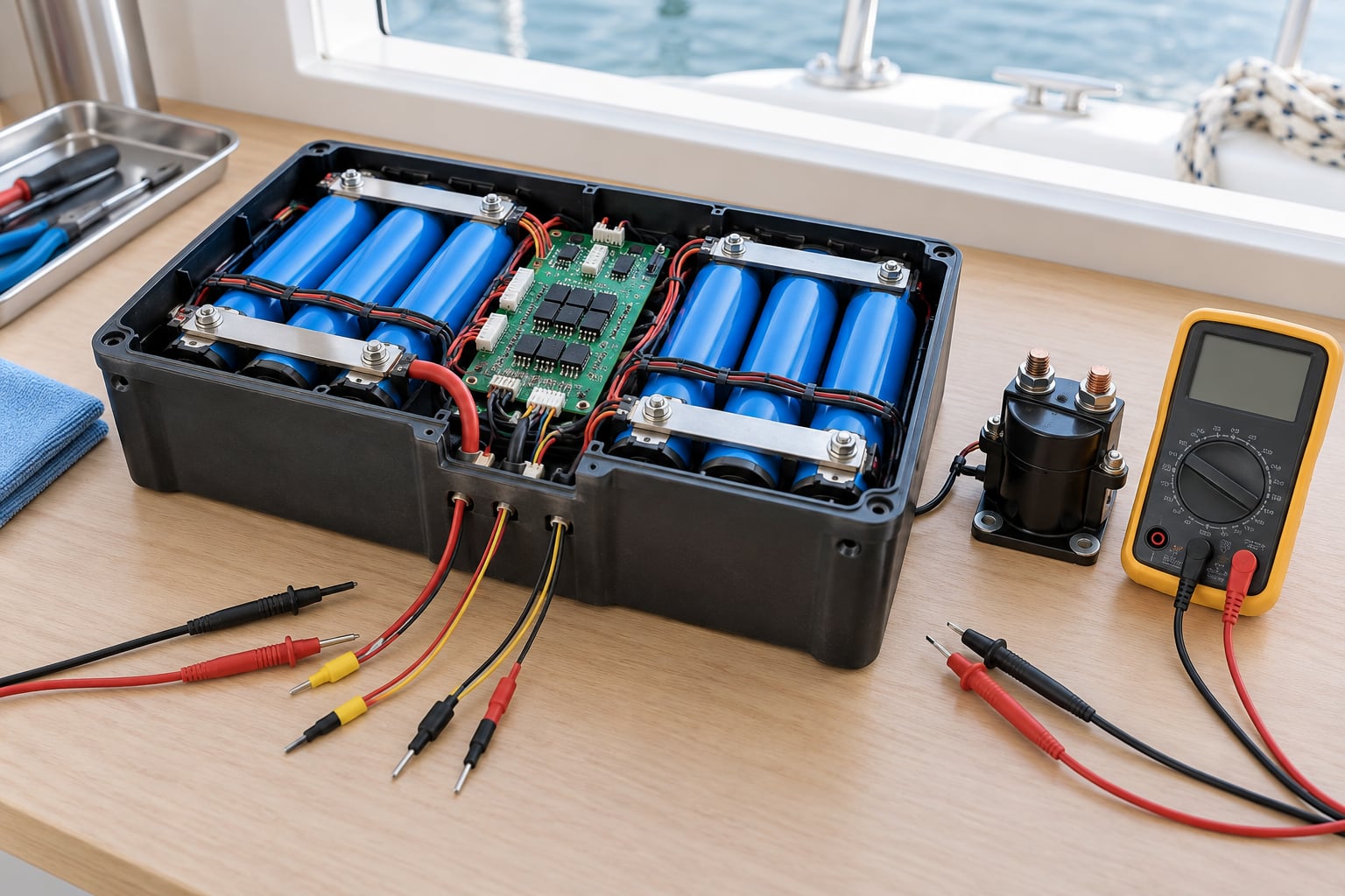
A battery management system is the electronic controller inside a battery pack that measures every cell’s voltage, the pack current and its temperature, then balances the cells, enforces safe limits and disconnects power when the pack strays outside its safe window. That is the whole idea behind how a battery management system works: one repeating loop that senses, measures, estimates, decides, acts, balances and reports. On a marine robot that loop runs while the hull is pitching in a short swell and the electronics sit behind a hatch that occasionally gets wet, so every part of it has to be boring and predictable.
Below is the short version before the detail:
- A battery management system, or BMS, sits between the cells and everything that draws power.
- It measures continuously, compares against limits set for your specific cells, and acts before damage happens.
- It also balances cells, estimates remaining energy, and reports status over a communication bus.
- It is not a charger, not a monitor and not a converter, though it coordinates closely with all three.
- Limits come from the cell manufacturer’s datasheet, never from an example on the internet.
This is the explanation I keep coming back to as of 2026, written for people who wire their own packs rather than buy a sealed one.
Table of Contents
- How a Battery Management System Works
- What Does a Battery Management System Do?
- How a Battery Management System Measures Battery Safety
- What Is Cell Balancing and Why Does It Matter?
- How a Battery Management System Estimates Charge and Remaining Range
- What Happens During Charging and Discharging?
- How Faults and Fail-Safe Protection Work
- How to Read Common Battery Management System Data
- What Safety Limits Should a Marine Robot Battery Use?
- What Can Go Wrong?
- Frequently Asked Questions
- What to Check First
How a Battery Management System Works
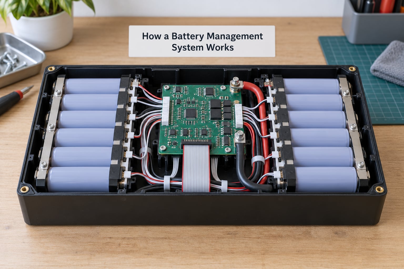
A battery management system works by watching a pack continuously and acting on what it reads, usually in a loop that repeats tens of times per second. The signal path is straightforward: cells in series, tap wires from every cell, an analog front end that converts those voltages into numbers, a microcontroller that reasons about the numbers, and power switches that either pass current to the load or stop it.
Because the cells are in series, the pack voltage is the sum of every cell voltage. That single fact drives the whole design. To know whether any one cell is safe, the BMS has to measure each cell on its own, which means one sense wire per cell, and the measurement hardware must tolerate the full stack voltage plus headroom.
Current is measured on the common path, usually with a shunt resistor that the pack current flows through, so the voltage across it can be converted into amps. On cheaper designs a hall-effect sensor replaces the shunt. Temperature comes from NTC thermistors bonded to cells or mounted between them, which change resistance as they warm.
Everything downstream, from motor controllers to radio links, is connected to the BMS output. When the BMS decides the pack is out of bounds, it opens that connection. On a small pack that is a couple of high-side MOSFETs acting as cut-off FETs. On a marine housebank or an ocean robot with a few kilowatts of propulsion, it is a pair of DC contactors rated for far more current, opened and closed through a pre-charge resistor so the load capacitors do not get slammed.
The microcontroller also decides when to sleep. Quiescent current in deep sleep can fall below 10 microamps, which matters when a robot spends weeks between missions and the pack has to survive without being topped up.
What Does a Battery Management System Do?
The core job is protection, estimation, balancing and communication, and it is worth being precise about what is not on that list. A BMS is not the charger: the charger decides how much current to push in and for how long, while the BMS can refuse that charge or disconnect the pack if limits are crossed.
A BMS is also not a battery monitor. A monitor displays numbers. A monitor has opinions about the numbers; the BMS acts on them. A cheap protection board on a hobby pack often does both jobs badly, which is why forum threads keep describing it as the weakest link in an otherwise good build.
Nor is it a power converter. A BMS does not step voltage up or down, does not regulate a DC bus and does not run your motors. It watches a pack and gates it.
In practice the functions break down like this:
- Protection. Overcharge, over-discharge, overcurrent, short circuit, excessive temperature and reverse charging all get cut off, usually in stages.
- Cell balancing. Small differences in cell voltage are levelled out over time so no single cell carries the whole pack’s stress.
- State estimation. The BMS works out state of charge, state of health, remaining energy and available power.
- Contactor and FET control. The physical path to the load is opened and closed, including the pre-charge sequence.
- Fault reporting. A fault code, a warning output or a message over the bus tells the operator or the vehicle controller what happened.
- Communication. CANbus and CANopen for vehicles and robotics, RS485 Modbus for long cable runs and industrial systems, UART for simple telemetry, Bluetooth for phones.
How a Battery Management System Measures Battery Safety
Safety decisions start as measurements, and the quality of those measurements decides how good the protection is. Voltage, current and temperature are sampled, converted to digital values, filtered, then compared against limits that were configured for your cells.
| Protective concern | What the BMS detects | Typical response |
|---|---|---|
| Overcharge | One or more cells above the upper cell voltage limit during charge | Stop charge current, then open the pack connection if it keeps rising |
| Over-discharge | One or more cells below the lower cell voltage limit under load | Warn, limit output, then disconnect to prevent deep discharge |
| Overcurrent and short circuit | Voltage across the current sensor exceeding the configured trip level | Hardware trip within microseconds, then a latched fault |
| Excessive temperature | Thermistor readings above the charge or discharge limit | Reduce current, stop charging, or lock out until the pack cools |
| Cell imbalance | Spread between the highest and lowest cell voltage | Enable balancing on the affected cells and cap the charge rate |
| Reverse charging | Current flowing into the pack from an external source | Block the path or refuse the charge request |
Those limits are not universal. A lithium-ion cell is commonly specified over roughly 3.0 to 4.1 volts, lithium iron phosphate has a different window entirely, and a pack assembled from older salvaged cells needs tighter limits than a new matched batch. Use the datasheet for the cells you actually bought.
How a battery management system works, one cell at a time
Each cell gets a tap wire routed to an analog front end, the chip that reads a stack of voltages and turns them into a digital stream the microcontroller can process. Its accuracy matters more than anything else in the chain. Analog-to-digital converter error of a few millivolts looks small on paper, but a few millivolts is a meaningful share of the margin between a healthy cell and a damaged one. Precision analog front ends are quoted at plus or minus 2 to 5 millivolts per channel.
Readings are taken as close together as possible. If the cells are sampled at different moments while current is flowing, the differences you see are partly measurement skew rather than real imbalance. Filtering then smooths noise without hiding a genuine trend, and the raw data is usually calibrated against a known reference at manufacture.
Long packs often use a daisy-chain isolator between modules instead of running a tap wire from every cell back to one board. The isolator passes the measurement signal down the chain and forwards it, which keeps long thin wires off the harness. It also means one damaged isolator can affect the cells downstream of it, which is worth knowing before you troubleshoot.
What Is Cell Balancing and Why Does It Matter?
Cell balancing is the process of keeping every cell in a series pack at nearly the same voltage, because the pack can only ever use the energy of its weakest cell. Cells always differ a little in capacity and internal resistance, and those differences grow with age, temperature history and current draw. Left alone, the strongest cells keep charging past the point where the weakest one is comfortable.
Passive balancing bleeds the excess off the higher cells through a resistor. It is simple, cheap and lossy, because the energy removed as heat comes out of the pack. Typical passive balancing current sits in the range of 30 to 150 milliamps per cell, and a good passive implementation keeps cells within about 10 millivolts of each other.
Active balancing moves charge from the stronger cells into the weaker ones with a small DC-DC converter, recovering most of the energy. Published designs reach around 90 percent efficiency and work at a few amps per channel. It costs more, adds components, and it is the usual choice for large packs where the balancing losses would be significant.
| Method | How charge moves | Typical current | Weak point |
|---|---|---|---|
| Passive | Bleeded through a resistor into heat | 30 to 150 mA per cell | Energy lost as heat; slow on large packs |
| Active | Transferred through a DC-DC converter | A few amps per cell | Cost, complexity, converter losses at low current |
Here is why imbalance costs energy, using an eight-cell pack as an example. Nameplate capacity is 3.2 Ah per cell at a nominal 3.2 volts, so roughly 82 watt-hours sit in the pack when new. Now suppose one cell has aged down to 2.4 Ah while the others are near 3.2 Ah.
| Cell | Nameplate capacity (Ah) | Usable capacity now (Ah) |
|---|---|---|
| Cell 1 | 3.2 | 3.1 |
| Cell 2 | 3.2 | 3.1 |
| Cell 3 | 3.2 | 3.1 |
| Cell 4 | 3.2 | 3.0 |
| Cell 5 | 3.2 | 3.0 |
| Cell 6 | 3.2 | 2.9 |
| Cell 7 | 3.2 | 2.9 |
| Cell 8 | 3.2 | 2.4 |
Without balancing, the pack delivers roughly what cell 8 can give, about 61 watt-hours rather than 82, and cell 8 then sits at its voltage limit while the rest of the pack is still holding charge. With balancing running, the eight cells track each other and the shortfall is visible and predictable instead of arriving suddenly at the end of a mission. Balancing cannot create capacity, but it stops the weak cell from being over-discharged and the strong ones overcharged while it does.
How a Battery Management System Estimates Charge and Remaining Range
Voltage alone gives a poor state-of-charge estimate, especially under load, because current causes voltage sag that looks exactly like a flat battery. A cell at rest might read 3.3 volts whether it is carrying a small load or pulling hard against a thruster, so the estimate would swing every time the motors spun up. That is why every serious BMS combines voltage with measured current.
The BMS estimates four different things, and confusing them is a common source of bad mission planning.
| Estimate | What it tells you | Typical method | Used for |
|---|---|---|---|
| State of charge (SOC) | How much charge the pack holds now, as a percentage | Coulomb counting blended with open-circuit-voltage lookup | Gauge displays and low-energy warnings |
| State of health (SOH) | How much original capacity the pack has lost | Comparing measured full-charge capacity with nameplate | Deciding when a pack needs replacing |
| State of energy (SOE) | Usable watt-hours remaining right now | Current SOC combined with present capacity | Mission and docking decisions |
| State of power (SOP) | The peak or continuous power available without exceeding limits | Voltage, temperature and current headroom | Throttling and motor sizing |
Coulomb counting integrates current over time: measure amps, multiply by the interval, add or subtract from a running total. The error comes from the shunt reading drifting over months, so good implementations blend in the open-circuit-voltage curve whenever the pack has been resting, which anchors the estimate and corrects the drift.
More advanced BMS firmware runs an extended Kalman filter, which models the cell’s internal state and corrects the estimate as measurements arrive. It handles voltage sag and temperature better than plain counting, and it is the reason some packs stay within a couple of percent of a laboratory reference while others wander by ten.
Marine conditions make this harder, not easier. Cold water raises internal resistance and reduces available power, wave motion makes current draw swing, salt spray and humidity corrode sense wires, and a pack that sat half-charged on a mooring for a month will not match its old behaviour. Plan on the conservative end of whatever range the BMS reports.
What Happens During Charging and Discharging?
Charging starts with a handshake: the charger asks the BMS for permission and for the pack’s limits, and the BMS answers only if the temperature is inside the charge window and no latched fault is present. That negotiation is why an unmatched charger and BMS is such a common headache in boat conversions, where the original charging voltage was never designed for lithium chemistry.
Once permitted, the pack follows the familiar constant current, constant voltage profile. During the constant current stage the BMS balances aggressively, because cell voltage differences are largest near full. During the constant voltage stage the current tapers and the BMS drops into a maintenance balance or stops balancing entirely. Charging below freezing is refused on most packs because lithium plating deposits metallic lithium on the anode instead of intercalating it into the graphite, and plated lithium can grow dendrites that eventually pierce the separator.
Under load the priorities shift. The BMS tracks current continuously, estimates state of charge, and throttles output if a cell approaches its lower limit. Many packs warn the operator first, reduce current second and disconnect only as a last resort, which is exactly the behaviour that annoys people who cannot tell whether a cutoff was a real fault or a setting they forgot to change.
Regenerative energy needs care. If braking or a recovering load pushes voltage back up, the BMS may divert that energy to auxiliary loads, to braking resistors, or simply dissipate it. On a sailing robot this usually means a resistor bank or a dump resistor, because there is no gearbox to dump it into.
How Faults and Fail-Safe Protection Work
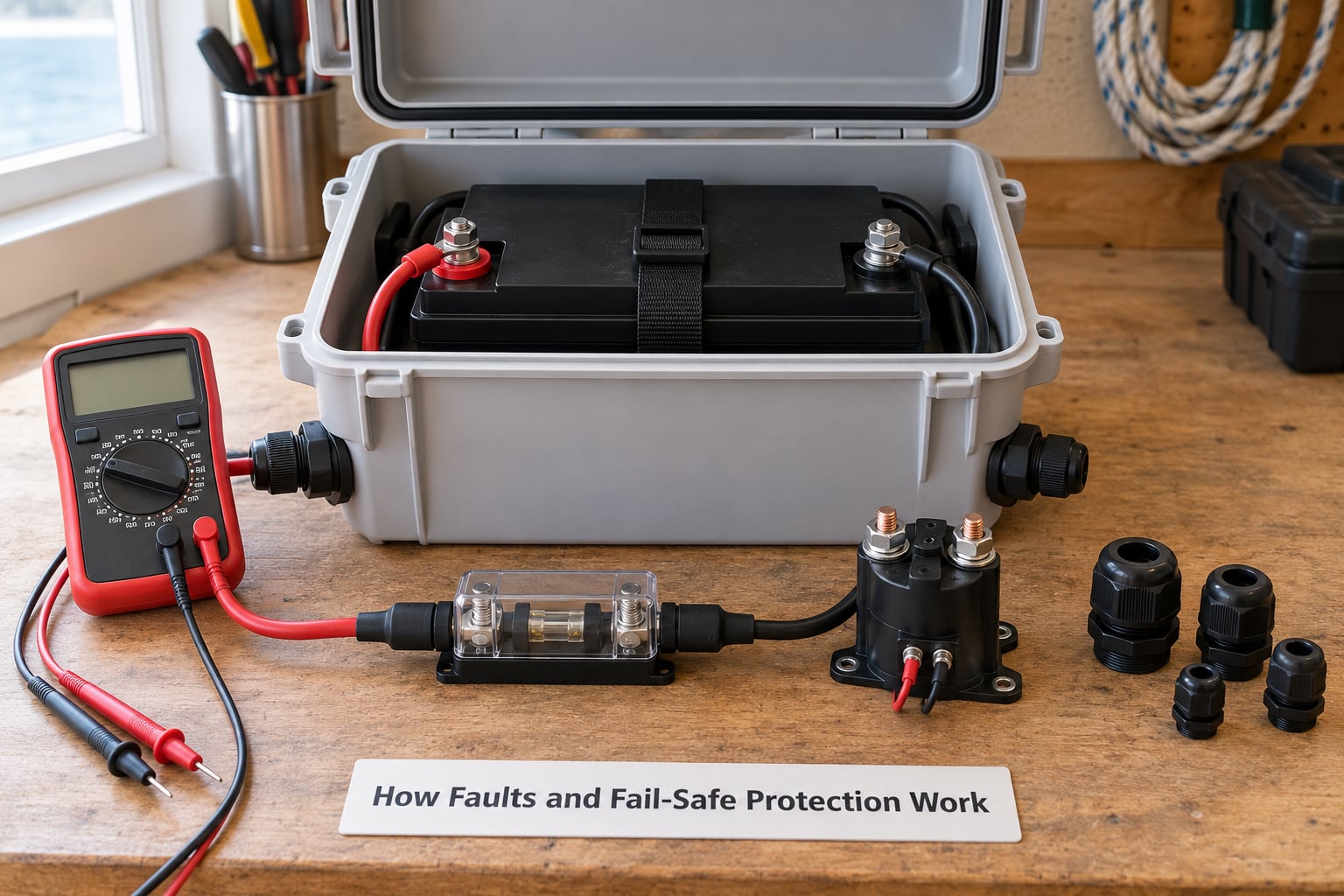
A fault escalates in stages rather than switching everything off at once. An abnormal reading first produces a stored fault flag and a warning output. If the condition persists, the BMS limits output current so the pack’s own load pushes it back inside the window. Only if that fails does it open the contactors, and after a latched fault the pack may need a deliberate reset rather than simply reconnecting.
Several layers sit above and below the BMS itself. External fuses catch a short that the BMS cannot see quickly enough, and they are still required because current through a spot-welded tab or a chafed cable can rise in microseconds. Contactors can weld closed, which is why a welded contactor means the pack stays live even when the BMS thinks it has disconnected, and why a parallel redundant contactor or a mechanical disconnect exists in serious designs. Communication loss with the vehicle control unit is itself treated as a fault, since a robot driving on stale battery data is a worse outcome than one that stops.
Sensor failures need the same suspicion. A thermistor that goes open circuit usually reads as extreme cold or extreme heat, and a sense wire that breaks can look like a deeply discharged cell. Both are usually easy to tell apart from a real event by checking whether several channels moved together or one moved alone.
Saltwater changes the arithmetic. It does not make electronics waterproof and it never will; it means corrosion, condensation and salt bridges are design inputs rather than surprises. Enclosures, glands, drip loops, conformal coating and a routine rinse with fresh water matter more to pack survival than any clever firmware. If you are sizing or wiring a high-power marine system, get a qualified marine electrical professional involved.
How to Read Common Battery Management System Data
Most BMS output is a handful of fields, and once you know what each one is deciding, the data becomes useful rather than decorative. Here is how to read the common ones on an autonomous platform.
- Pack voltage. The sum of all cells. Useful as a sanity check, poor as a state-of-charge source under load.
- Current. Signed pack current, positive on discharge. Check that it matches what your instruments say; a factor-of-ten error here is common.
- State of charge. Use it as a planning number, not a measurement. Verify it occasionally against a rested voltage measurement.
- State of health. A falling figure means replacement planning, not an emergency.
- Maximum and minimum cell voltage. The pair you actually watch. Their difference is your imbalance figure.
- Pack and cell temperature. Temperature usually limits charge long before voltage does.
- Imbalance or delta value. Compare against the BMS’s own configured threshold, not against a number from a forum post.
- Fault and warning flags. Read these before resetting anything. A reset clears the symptom, not the cause.
- Contactors or MOSFET state. If this reads closed while the pack is dead, suspect a welded contactor or a blown fuse.
- Balancing active. If this never turns on during a full charge, either the cells are already close or the balancing circuit is not working.
One honest warning from practitioners: the datasheet is a claim, and a measurement is a fact. Log the values across a real charge and discharge cycle and compare them with what the BMS reported.
What Safety Limits Should a Marine Robot Battery Use?
Use the limits published by the cell and pack manufacturer for the cells you fitted, and nothing else. Numbers copied from an unrelated example are the most common cause of a BMS that cuts out on a perfectly healthy pack, or worse, one that never trips at all.
A few design considerations matter more for marine work than they do on land. High-current propulsion asks for low internal resistance, short, well-supported cable runs and contactors rated well above your peak current, with the pre-charge sequence handled properly. Vibration from engines, waves and impacts argues for strain relief at every terminal, mechanical support for the cells, and connectors rated for the environment rather than a dry indoor one.
Enclosure ingress protection is a mechanical decision, not a firmware setting. Include a fuse sized to the cable, not just to the cells, so a fault upstream of the BMS is caught. Add a way to disconnect the pack mechanically for maintenance, and give the operator a clear, reachable emergency shutdown that does not depend on telemetry or a radio link.
Follow the cell manufacturer’s instructions for charging, storage temperature and maximum charge current. For any hazardous or high-power work, involve a qualified marine electrical professional rather than working from a general guide.
What Can Go Wrong?
Almost every BMS failure I have read about traces back to something mundane at the other end of the sense wires. The table pairs the common ones with a sensible first diagnostic.
| Problem | What you observe | First diagnostic and prevention |
|---|---|---|
| Loose cell connection | One cell reads wildly high or low, readings jump when the hull moves | Measure each tap at the board and at the cell; torque terminals and add strain relief |
| Wired out of order | Several adjacent cells report similar voltages that should differ | Compare tap order against the cell order in the diagram; verify before first power-up |
| Mismatched cells | Permanent imbalance that balancing cannot close | Log each cell’s capacity on a bench; use cells of the same batch and age |
| Temperature sensor fault | Pack refuses to charge in mild conditions, or reads extreme heat | Check thermistor resistance against the datasheet curve; insulate sensors from heat sinks |
| Inadequate cooling | Charge acceptance drops during a long mission | Log cell temperature during charge; move the pack away from heat sources and seawater |
| Incompatible charger | Pack will not charge, or drops out under load | Compare charger voltage and current with the BMS limits; update settings to the cell datasheet |
| Moisture entry | Intermittent faults that worsen in wet conditions | Open the enclosure dry, inspect glands and seals, rinse with fresh water after each outing |
| Damaged leads | Voltage drops under load, heat at a terminal | Check cable gauge against peak current and inspect for chafing near moving parts |
When a BMS refuses to cooperate, work in this order: measure every cell voltage by hand, measure temperatures, confirm the limits match the cells and charger, then check the connections. Most “dead” packs are a sensor wire or a charge setting.
Frequently Asked Questions
Is a battery management system the same as a battery monitor?
No. A monitor is read-only: it measures voltage, current and temperature and shows you numbers, usually over Bluetooth or a display. A BMS closes the loop. It enforces the limits the monitor displays, opens contactors when a limit is crossed, moves charge between cells during balancing and stores fault codes. A monitor tells you the pack is empty. A BMS works to stop it getting there.
Do I need a BMS with my marine battery charger?
You need both, and they must agree with each other. The charger sets the current and voltage profile, while the BMS holds the pack inside its limits and can refuse or interrupt the charge. Mismatched settings are a common reason a pack will not charge at all or drops out under load. Match the charge voltage and current to the cell datasheet, and confirm the BMS permits charging at the temperature the boat will actually see.
Why does my battery show a low charge immediately after charging?
Three things usually cause it. The pack was only partly charged because the charger tapered off early. The BMS is still finishing a balancing or maintenance cycle and is reporting a deliberately conservative figure. Or the load spiked the moment charging stopped and voltage sag dragged the estimate down. Measure individual cells against the pack total, watch the reading settle after the charger disconnects, and confirm the fuel gauge is calibrated against a real measurement.
Can a BMS protect a battery from water damage?
Partly, and it is not the right tool for the job. A BMS acts on the signals it can measure, so it can notice a short, abnormal current draw or an open-circuit sensor once water reaches the sense wires. It cannot keep seawater out of an enclosure, stop corrosion on terminals or repair a flooded board. Sealing, glands, drip loops, drainage and routine rinsing with fresh water are mechanical decisions that sit in front of the electronics.
How do I safely test a battery management system?
Test on a bench with a pack you can handle and no load attached. Measure every cell voltage and compare the spread against the manufacturer’s limit. Check temperature sensors against a reference. Confirm the contactor opens on a safely triggered over-current or over-temperature condition, and that the charger is refused when the BMS says no. Wear eye protection, keep metal tools away from the terminals and do all of it dry.
What to Check First
If you are picking up a pack you have not trusted yet, start with paperwork and finish with a dry bench test. Read the cell datasheet, confirm the pack’s cell count and series arrangement match what the BMS expects, and check that the configured limits and the charger settings both come from that datasheet rather than from a forum post.
Then measure every cell voltage and every temperature by hand with the pack at rest, and compare the spread against the BMS’s own imbalance threshold. Inspect the connections, the tap wire order and the enclosure seals while the pack is dry. Confirm the fault path works by triggering a condition you can safely cause, such as blocking one thermistor, and watch the contactor actually open.
Only after all of that should the robot go in the water. A BMS is a small board doing a large job, and the failures it cannot prevent are usually mechanical: a chafed cable, a loose terminal or a hatch that lets spray in.