Thermal runaway is a self-accelerating reaction inside a lithium cell: exothermic chemistry generates heat faster than the cell can shed it, carrying temperature from SEI decomposition around 130-150°C through separator failure and electrolyte venting, with combustion above roughly 600°C. Once that feedback loop outruns dissipation, no external intervention stops the cell itself.
So learning how to prevent thermal runaway in battery packs is not about reacting faster.
Table of Contents
- Quick Answer: How to Prevent Thermal Runaway in Battery Packs
- What You Need
- Step-by-Step
- 1. Select Cells and a Protection Architecture
- 2. Set Conservative Electrical and Thermal Limits
- 3. Add Fuses, Contactors and Fault Isolation
- 4. Provide Temperature and Gas Monitoring
- 5. Design a Safe Enclosure and Ventilation Path
- 6. Validate the Pack Before Connecting a Load
- 7. Operate, Charge and Maintain the Pack Safely
- 8. Respond to Warning Signs or a Thermal Event
- Common Mistakes
- Frequently Asked Questions
- Conclusion
Quick Answer: How to Prevent Thermal Runaway in Battery Packs
- Choose a chemistry with thermal headroom for the application and its environment.
- Buy traceable, matched cells and record the batch with the pack.
- Keep every cell inside its datasheet voltage and temperature window.
- Watch per-cell voltage and temperature, including the rate of temperature rise.
- Protect with fuses and contactors that act when firmware does not.
- Space cells and modules so one event cannot reach the next.
- Keep heat out with the right passive or active thermal management.
- Give vented gas a designed path and a monitored, staged test before service.
It is about never letting initiation start, and slowing any cell that does go into propagation long enough to isolate it. That means a chemistry-aware design, hardware protection that works when firmware does not, staged validation before a load ever connects, and an operating discipline matched to where the pack actually lives. For a marine robotics pack sitting in salt spray and vibration, those last two matter as much as the cell choice.
Everything below follows the cell and pack manufacturer’s safety data and owner documentation. Generic limits on the internet are not a substitute for your datasheet.
Two problems get confused here, and separating them makes the whole subject clearer. Initiation is the moment one cell starts heating itself. Propagation is the moment its neighbours follow, through conduction, radiation and molten material. Layer 1 to layer 4 of this guide attack initiation. Layers 5, 6 and 7 attack propagation. A pack that only handles initiation can still be destroyed by one bad cell, because a cell in runaway can take its whole module with it within minutes.
This is the framing that keeps an unattended marine or sensor-node pack honest: nobody is standing next to it when the first cell goes, so the layers that need a human present are the ones you have to automate.
What You Need
Start with the chemistry. LiFePO4, NMC, NCA and LTO have different charge ceilings, discharge temperature windows and failure behaviour, and the protective design follows from that choice rather than the other way round.
- Manufacturer documentation: the cell datasheet, safety data sheet, and the pack owner’s manual. These set charge ceilings, temperature limits, C-rate limits and storage conditions.
- Cell specifications: nominal and maximum charge voltage, continuous and peak discharge current, cell matching and traceability data.
- Protection hardware: correctly rated fuses, a contactor or precharge circuit, per-cell fuses where branch isolation is needed.
- Monitoring equipment: a battery management system with per-cell voltage taps and cell-level temperature monitoring, plus whatever telemetry link the deployment can carry.
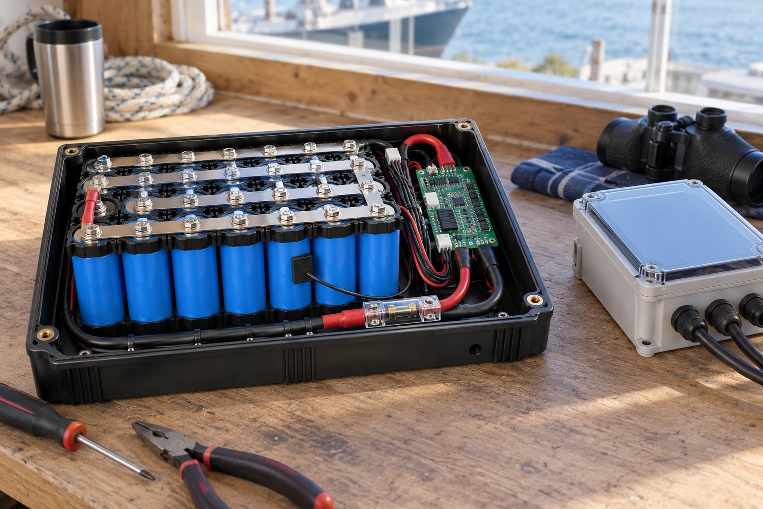
- Enclosure materials: a corrosion-resistant housing, insulation, cable strain relief, and any venting arrangement the pack manufacturer approves.
- Emergency equipment: an appropriate extinguishing agent for the chemistry, eye protection, gloves rated for the voltage, and a plan for calling emergency services.
Two of those deserve emphasis before anything else. The datasheet is the only document that tells you the actual limits for your cells, and the telemetry link matters more than people expect, because an unattended pack is where detection lag becomes the difference between an isolated cell and a lost vessel.
Step-by-Step
Here is the same eight layers in one place, with the mechanism and what each one actually stops. The last column matters most, because layers that sound impressive often stop something you did not care about.
| Layer | Mechanism | What it stops | What it cannot stop |
|---|---|---|---|
| Cell and chemistry choice | Onset temperature and thermal stability of the cell | Most initiation events, before they start | A cell that is physically damaged |
| Cell matching and traceability | Consistent capacity and impedance across the batch | The weak-link cell drifting out of line | Ageing-related drift over time |
| Operating limits | Voltage, current and temperature ceilings below the datasheet | Overcharge and the abuse that causes it | Exceeding them through a misconfigured charger |
| BMS monitoring | Per-cell voltage and temperature, rate of rise, balancing | Early detection and controlled shutdown | Anything, if the sensor or contactor has failed |
| Fuses and contactors | Independent hardware interruption of fault current | A short spreading through the whole pack | A single cell venting inside a sealed module |
| Cell spacing and barriers | Thermal barriers and compression between cells | Propagation from cell to neighbour | The initiating cell itself |
| Thermal management | Heat kept below onset through conduction, phase change, air, liquid or immersion | Everything downstream, by never reaching the threshold | A cell heated from outside the cooling path |
| Enclosure and vent path | Containment plus a designed route for vented gas | Gas reaching occupants and ignition sources | Initiation, and the vent path needs a real design |
1. Select Cells and a Protection Architecture
Risk starts with the cell, and it is shaped by more than chemistry. Age matters, because degradation raises internal resistance and makes heat generation under load less predictable. Capacity, discharge rate and C-rating set how much heat the cell makes doing ordinary work.
Matching and traceability decide whether you can detect a weak cell before it becomes a hot one. Buy cells from one production batch with documented capacity and impedance matching, and keep the batch records with the pack. A pack assembled from cells nobody can trace is a pack you cannot condition.
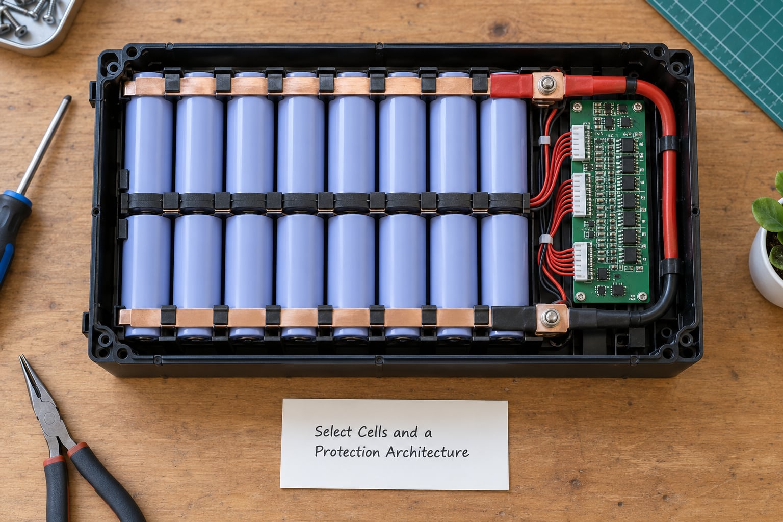
Then design the architecture around them: series balance, physical spacing between cells so conduction has to travel through a barrier, sensors at the positions that actually run hot, and a properly engineered battery management system matched to the load rather than a generic board with more channels than you need.
2. Set Conservative Electrical and Thermal Limits
Limits come from the datasheet, then get a margin. Charge current ceiling, discharge current ceiling, cell voltage window, maximum cell temperature, minimum charge temperature, and the state-of-charge range you allow in service.
For nickel-based chemistries the overcharge ceiling is often around 4.2 V per cell; going past it forces electrolyte oxidation that runs exothermically. That single number is why a charger with the wrong termination settings is more dangerous than almost anything else in the design.
Set alarm thresholds below your trip thresholds, and both below the datasheet limit. High-current marine loads add a second reason to keep pack-level protection: a thruster or winch can pull a current spike that pushes a marginal cell into a corner the BMS sampling rate never catches.
3. Add Fuses, Contactors and Fault Isolation
Fuses are selected for the wire, the load and the battery’s available fault current, not by a generic “the load draws X amps” rule. Under-sizing the fuse invites a fire; over-sizing it removes the protection you paid for.
Splitting a pack into separately fused branches limits how much energy one fault can reach. If one cell shorts, you want the fault energy bounded by one branch rather than by the whole pack. Per-cell fuses do this well on series strings but add resistance and cost, so weigh them against your fault analysis.
A contactor with a precharge circuit protects the DC bus and the capacitors downstream from inrush at startup. Check that it opens on loss of control signal and on BMS trip, not only on the happy path.
4. Provide Temperature and Gas Monitoring
Put temperature sensors where the heat actually is. Sensors at the pack edge read ambient, not a hotspot. If you can only afford a few, spend them on the geometric centre of the most loaded module, near the high-current terminals, and adjacent to any cell with a history of running warmer.
Track the rate of rise, not just the reading. A healthy cell under load warms slowly and predictably. A cell entering trouble warms fast, so a dT/dt threshold and a per-cell temperature delta against the pack average catch trouble that an absolute limit would miss.
Gas, smoke or pressure detection adds an earlier trigger, and the appropriate medium depends on chemistry. For field deployments, decide in advance which telemetry signals trigger a controlled shutdown and which trigger an alert to a human, and make sure somebody is actually watching that channel.
5. Design a Safe Enclosure and Ventilation Path
The enclosure has four jobs: resist corrosion, keep water out, hold the cells apart from heat sources, and give vented gas a path it can leave by. Marine service makes the first two the hard ones. Salt spray attacks connectors and busbars, condensation forms on cold surfaces in a sealed box, and standing water in a bilge finds any seam you missed.
Use stainless hardware in saltwater service, specify connector bodies rated for the exposure, add strain relief so vibration cannot work a terminal loose, and separate the pack from chargers, regulators and any other heat source. Restrict access to high-voltage conductors and provide the manufacturer-approved venting or containment arrangement.
Be honest about what sealing achieves. A sealed enclosure keeps water out and keeps ignition sources away. It does not stop a cell from going into runaway, and an enclosure with no designed vent path turns vented gas into a pressure problem. Vent where the gas can harmlessly go, away from occupants.
6. Validate the Pack Before Connecting a Load
Write the test procedure first. Then work through it: visual inspection of every cell, busbar and connection, polarity check, insulation resistance check, cell balance verification, sensor calibration against a known reference, and a review of the BMS firmware thresholds against your datasheet limits.
Bring the pack up in stages. Start at a low current, confirm the protection thresholds actually operate at the values you configured rather than the defaults, then increase load and charge current only after each stage behaves. Testing an unproven pack at full load is how a commissioning mistake becomes a hull fire.
Record the results. The document that shows your thresholds were verified is also what tells the next person what was checked.
Where the pack is a commercial product rather than your own build, lean on the standards that already encode this work instead of reinventing it. UL 1973 and IEC 62619 cover battery and cell safety testing, UL 9540A is the test method used to evaluate how a cell behaves under thermal abuse and whether it propagates, IEC 62477-1 covers electrical safety in energy storage, IEC 62133 covers portable sealed cells, UN 38.3 covers transport, and GB 38031 is the Chinese standard that added explicit propagation requirements. A cell that has been through a propagation test tells you more than any datasheet claim, because the test answers the question the datasheet cannot: what does this cell do when it goes?
7. Operate, Charge and Maintain the Pack Safely
Charge where someone can see it and reach it. Unattended charging is the single most avoidable risk in the whole sequence, and it is also the one most field deployments take by necessity, which means those deployments need remote monitoring rather than an optimistic assumption.
Follow the charger and BMS requirements exactly, including termination behaviour and any temperature preconditioning. Log temperature history so you have a baseline to compare against later.
In marine and field service, inspection frequency should follow the stressors. Salt and moisture raise connector and corrosion checks. Vibration raises connection checks and the retirement age of crimps and strain relief. Every thermal cycle widens the range of normal readings, so trend data beats a spot check.
A reasonable routine is a quick visual and connector check before every deployment, a thermal check under load on the first day out, and a deeper inspection that covers terminals, enclosure seals and sensor readings at whatever interval your duty cycle implies. For a pack on a hull, that is usually weeks, not years. What matters more than the interval is having a written baseline to compare against, because a connector reading that has drifted from last month is the actual warning.
8. Respond to Warning Signs or a Thermal Event
Warning signs: heat you cannot explain, a sharp or solvent-like smell, smoke, visible swelling, hissing, venting, or a temperature rise past your defined alarm threshold. Rising temperature in one module while the rest of the pack reads normal is the pattern worth taking seriously.
The response sequence, in order: raise the alarm and tell anyone nearby. De-energize only if that can be done safely without approaching a hot or venting pack. Evacuate the area and account for everyone. Call emergency services. Follow your local battery and fire-safety guidance from that point.
Do not improvise handling of a damaged pack. Vent cells can rupture without warning, and moving a swollen or venting assembly tends to make the outcome worse. On a vessel, that also means closing watertight boundaries and getting clear of the gas path before the event develops.
Common Mistakes
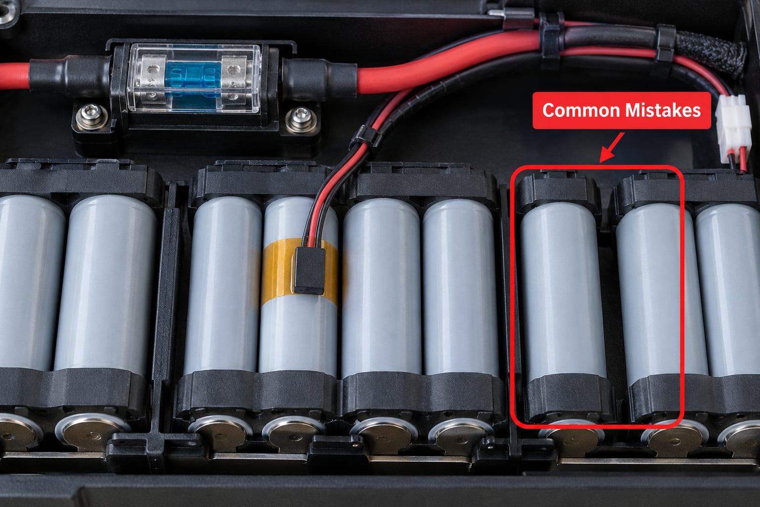
These are the errors that show up repeatedly, and each has a straightforward correction.
- Undersized wiring and fuses. Correct by sizing conductors for the load, voltage drop and fault current, then sizing the fuse from that analysis rather than from a rule of thumb.
- Charging outside the specified range. Correct with a charger matched to the chemistry and a BMS charge limit below the datasheet ceiling.
- Ignoring cell imbalance. Correct with per-cell monitoring and balancing, and by retiring packs whose spread exceeds the datasheet limit.
- Relying on software without hardware protection. Firmware can hang, fail an update or sit misconfigured for a season. Correct by adding fuses and contactors that act without software.
- Placing sensors only at the pack edge. Correct by sensing at the geometric centre, near high-current terminals, and on the modules that run hottest.
- Using incompatible chargers. Correct by verifying the charger’s chemistry profile, termination voltage and temperature compensation against the datasheet.
- Allowing saltwater exposure. Correct with a suitable enclosure rating, corrosion-resistant hardware, connector bodies rated for the exposure and a routine connector inspection.
- Testing without staged limits. Correct by validating protection thresholds at low current and increasing load only after each stage passes.
- Treating a swollen or damaged pack as reusable. Correct by quarantining it, following local guidance for damaged lithium batteries and never reusing it.
- Assuming a sealed enclosure solves the problem. Sealing blocks water and ignition sources. It does not prevent initiation, and it removes the vent path gas needs.
One more deserves calling out for marine work: cooling pumps and fans are single points of failure. If the only thing standing between your cells and a hotspot is one pump, treat that pump as safety-critical hardware with monitoring, a defined failure response and a fallback path.
On LFP specifically, buyers sometimes assume vent risk disappears entirely. It doesn’t. An LFP cell in thermal runaway can release a larger volume of explosive gas than lead-acid off-gassing from overcharging, so design the ventilation path for gas, not just for flame.
Frequently Asked Questions
How do you stop thermal runaway in batteries?
You mostly cannot, once a cell has entered full runaway, so prevention is the real answer: keep cells inside their datasheet temperature and voltage windows, use a BMS with per-cell voltage and temperature monitoring, protect cells physically from damage, and add fuses so one fault cannot spread. If a cell starts heating abnormally, isolate the pack and stop charging. Cooling and venting manage the event; they do not reverse the reaction.
Do LiFePO4 batteries suffer from thermal runaway?
Yes, though less readily than nickel-based chemistries. LFP cells have a higher onset temperature and a flatter voltage curve, which makes overcharge faults less likely to go unnoticed, but a damaged or overcharged LFP cell can still run away. Do not treat it as vent-risk-free: gas volume from an LFP cell in runaway can exceed lead-acid off-gassing, so your enclosure and vent path still matter.
What causes thermal runaway in lithium-ion batteries?
The usual triggers are an internal short circuit from mechanical damage or a dendrite penetrating the separator, overcharge past the cell’s ceiling voltage, physical crushing or puncture, external heat such as a nearby fire, and manufacturing defects. The most effective single measure is keeping cells inside their rated temperature range during charge and discharge. Any of these can start the SEI decomposition that leads into venting and full runaway.
Which battery type is most prone to thermal runaway?
Nickel-based chemistries such as NMC and NCA are generally the most prone, because their higher energy density packs more heat release into a smaller volume and their charge ceiling is easy to overshoot. LiFePO4 has a higher onset temperature and better thermal stability. LTO is more tolerant still but has lower energy density. Chemistry is only one factor, though: age, damage and charge control matter enormously.
How hot does a battery get during thermal runaway?
SEI decomposition begins somewhere around 130-150°C, cells typically vent between about 150°C and 200°C, and combustion can push well past 600°C. Cells around the failing one rise with it, which is why propagation is the problem to design against. Treat any cell exceeding your defined alarm threshold as an incident, not as a reading to be averaged into the pack statistics.
Can a battery fire be put out with water?
Cooling is what matters, and water is effective at that, which is why suppression media in packs are usually aimed at heat removal rather than flame. What water cannot do is stop the chemistry inside a cell, so a cell in runaway will keep generating heat once the water is gone. Never improvise handling of a hot or venting pack: back off, evacuate, call emergency services and follow local guidance.
Conclusion
Learning how to prevent thermal runaway in battery packs comes down to a handful of decisions made once, at design time. Identify the chemistry and pull its actual limits from the manufacturer’s documentation rather than from a generic chart. Install hardware protection that acts even when the firmware does not, and put sensors where heat actually appears. Validate monitoring and fault isolation in a documented, staged test before a load connects. Then write the response plan while everyone is calm, because in a bilge or an enclosed hull there is rarely time to think one up.
That plan is the difference between a builder who manages an incident and a builder who gets a call from the coastguard.