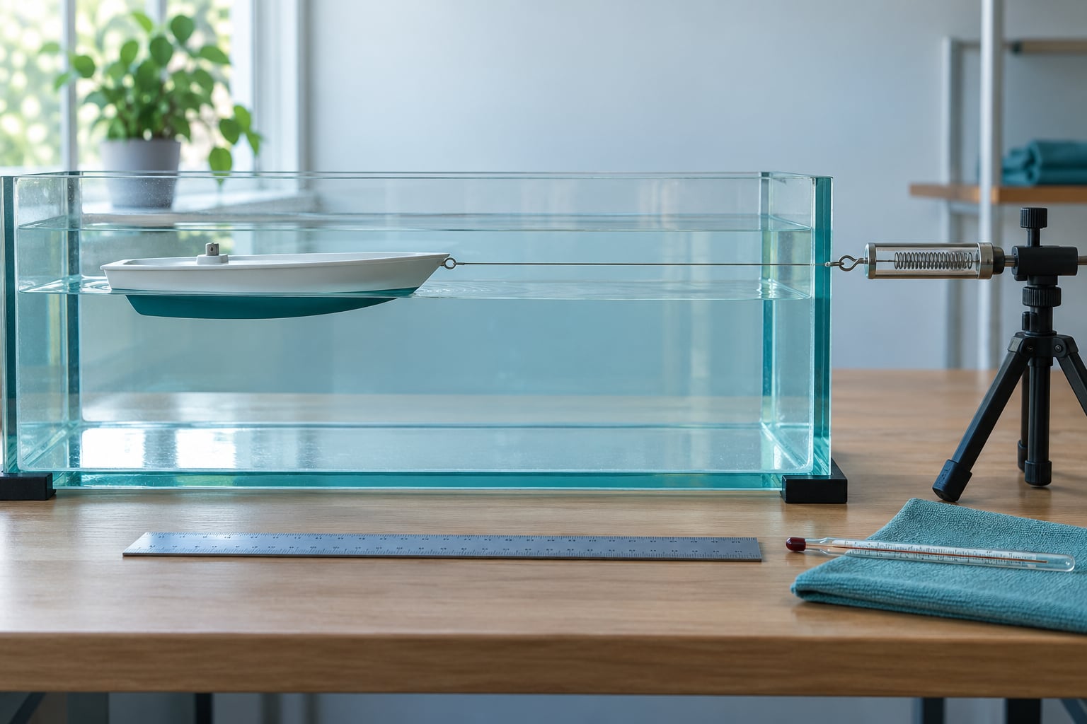
The cheapest trustworthy way to test drag on a model hull is a calm-water tow test: float the model at the depth and trim it will actually run at, pull it through a still tank or basin at a constant known speed, and read the steady force on a spring scale or hanging scale. Do three or more runs per speed, hold everything else identical, and compare hulls against each other rather than against a theoretical number. A whole session takes an evening once the rig is set up.
The catch is that most home tank tests do not fail because of the scale. They fail because the model sits at a different trim than it would at speed, the tank is too narrow so the walls add drag, or someone compares two runs made hours apart with the water at a different level. Get those three right and the numbers are good enough to rank two designs against each other, which is usually the whole point.
Start with the hull itself and a tank where it can run straight. Everything else is optional instrumentation, and you can add it as the questions get harder.
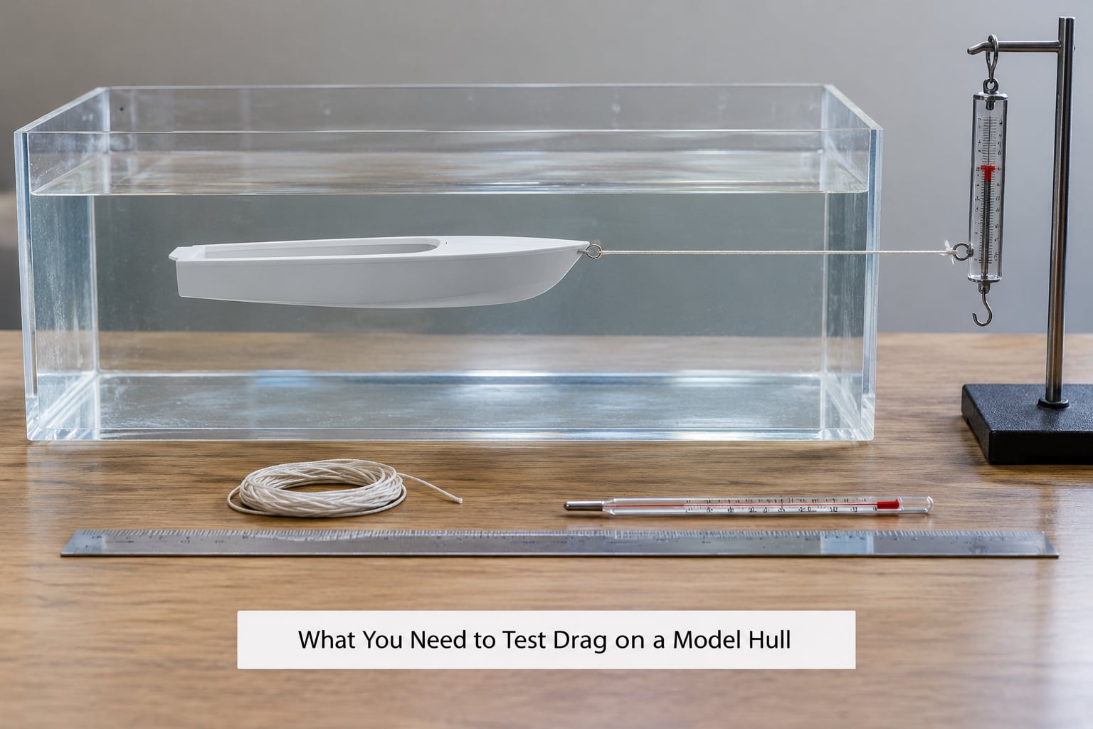
A calm test basin. A stock tank, a large storage tote, a garden pond or a rowing-boat-length section of flat water all work. Wall effect is the thing to watch: a hull should have roughly one hull length of clear water ahead of it and one width of clear water beside it, otherwise the confined flow raises the reading. If that is impossible, say so in your notes, because the number becomes comparative only.
A tow point and a tow line that will not stretch. Braided or low-stretch line, plus a rigid connection to the model. Monofilament and elastic rope stretch under load and quietly corrupt the reading.
A force gauge. A calibrated spring scale or digital hanging scale in the low-kilogram range covers most hobby work. A load cell with a display gives you better resolution if you want to chase small differences between two hulls.
A speed reference. A marked distance along the tank, a stopwatch, and a floating marker or gate at each end. Time between two fixed marks and you get speed without a flow meter.
Depth and trim control. A thin shaft from above, a rear trim tab, and a rigid bracket or tray for ballast. This is the part most home rigs leave out and most results depend on.
A thermometer and a note of how long the tank has been settling. Water temperature and dissolved minerals both shift drag by a few percent between sessions.
Optional: a camera on a tripod at the tank side, level with the waterline. It catches trim, porpoising and a wobbling tow line that you would miss by eye, and it turns the run into something you can re-examine later.
For budget tiers: a tote, a braided line and a spring scale gives you a working baseline. Add a digital hanging scale and a camera and you can resolve differences of a few percent. A load cell, a proper carriage and a flow meter put you in professional territory, where facilities measure drag to standards published by the International Towing Tank Conference.
Step-by-Step
The sequence below runs from picking a test condition to recording a number you can repeat next month. Throughout it, keep three things apart in your head, because most arguments about bad results are really arguments about which of the three failed.
Apparent resistance is whatever the gauge read, including everything the tank, the line and the trim added to the hull. Useful comparative drag is the difference between two runs where all of that was held fixed, and it is the only number most builders should trust. Instrument-calibration error is a zero that drifted or a scale with steps too coarse to resolve the difference you are chasing. Check the third before you believe the second.
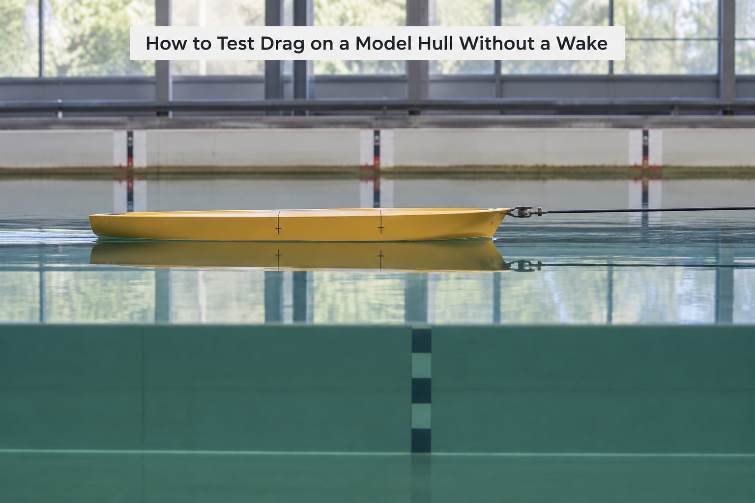
How to Test Drag on a Model Hull Without a Wake
Fill the tank to a marked depth and let it settle. Put a fixed reference on the side of the tank at the waterline so you can see the model ride at the height you intend.
Align the model with the tank centreline and make the tow point sit at the depth you want to test. A common mistake is testing a hull designed to run on the surface and towing it fully submerged, or the reverse; both are valid tests, but only if you name which one you did.
Keep the tow line taut and horizontal. A sagging line adds drag of its own and lets the hull wander, which changes trim mid-run. Then move at a low speed first, low enough that the hull does not push up a bow wave, and only then step up.
Hold speed steady by watching the clock at the two tank marks. Read the force once the model has been at speed for several seconds and the reading has stopped moving. Three consecutive readings that agree within the resolution of your gauge means the run is stable and you can write it down.
Measure Resistance at Several Speeds
One speed tells you almost nothing. Drag rises roughly with the square of speed for a fixed hull, so a single point can be explained by any of several problems. Run at least three speeds spread across the range you care about.
Write force and speed for each setpoint, then plot them. A near-straight line through the origin, with force proportional to speed squared, means you are measuring resistance and not an offset. A line that does not pass near zero force at zero speed usually means a zeroing problem rather than a hull problem.
Look for the trend, not the reading. Hulls that differ mainly in wetted surface separate further apart as speed rises; hulls that differ mainly in appendage drag show a gap that grows early and then flattens. Two hulls whose curves sit on top of each other across three speeds are, for your purposes, the same hull.
Control Depth, Trim, and Mounting
Ships are tested at the depth they will actually run at, and so should yours. Set the model so the wetted area and trim angle match the intended condition, and note the trim as an angle from the marks rather than as a vague description.
Pitch and roll have to be suppressed. A rear trim tab handles most of it on a small model; a light restraint on a flexible appendage can help more than it hurts. If the model is porpoising, fix that before collecting data, because porpoising changes the reading continuously and makes the run unrepeatable.
Then write down the mounting method in enough detail that someone else could rebuild it: what the bracket is made of, where the ballast tray sits, how far below the waterline the hull rides, and whether the tow point is on the centreline or offset. An unattached mass changes the hull, and a half-documented rig guarantees a different answer six weeks later.
Compare Multiple Hulls Fairly
When you want to rank designs rather than produce an absolute number, the comparison method is simpler and more reliable than calibration. Keep the tank water level identical for the whole series, and do not top up between hulls.
Condition each hull the same way. Every hull gets soaked to equilibrium for the same time before its first run, gets the same surface finish, and carries ballast to the same immersion depth. A hull that has been soaking for an hour and one straight from the shelf are not comparable.
Run in alternating order, hull A then hull B then A then B, rather than finishing all of A’s runs before starting B. Drift in water temperature, a slowly rising surface film, or a mount loosening over the session then spreads across both hulls instead of penalising whichever one went second.
Do at least three runs of each hull at each speed, discard nothing without writing down why, and compare averages. If you want the near-freeight version, the yoke rig described on the boatdesign.net thread does the same job: a stick balanced at the centre with a model tied to each end, and the hull that pulls hardest is the draggier one.
Check Water Conditions and Repeatability
Zero the force gauge at the start of every session, with the line attached but the hull out of the water, and re-zero it at the end. If those two zeroes disagree, the reading drifted during the session and you should say so rather than quietly averaging it away.
Log water temperature, the time since the tank was last disturbed, and whether a film or dust is on the surface. Give the water time to settle after filling or after anything moved in it; a tank that is still moving gives you high readings that will not repeat.
Discard an outlier only when you have a physical reason. A pass that caught the hull, a line that fouled a bracket, a gust across the surface: those runs are invalid, not unlucky. If the outlier has no explanation, keep it and report the wider spread, because a number with a wide error band you have stated honestly is more useful than a tidy average that hides a problem.
A reasonable reporting format is the mean force per speed, the number of runs behind it, and the spread between the fastest and slowest run. If the spread is bigger than the difference between your two hulls, you need a better gauge or more repeats, not a conclusion.
Common Mistakes
Comparing runs at different depths. Depth changes wetted area and trim, and drag follows. Mark a fixed waterline on the tank and refill to it every session.
A flexible or sagging tow line. Stretchy line adds spring energy and lets the hull wander. Use low-stretch line, keep the pull horizontal, and check the line is not touching anything.
Creating a wake. A bow wave is real physics, not an error, but at low speed it can dominate everything else you are trying to measure. If you are separating hull forms, run slow enough to stay below the wave-making regime and say that you did.
Not zeroing the gauge. A hanging scale that has been hanging all day reads differently from one zeroed this morning. Zero before and after.
Changing trim between runs. Small weight shifts in the ballast tray can change the ride enough to swamp the difference you are testing. Mark the tray position and re-check it every run.
Reading resistance as drag. A rising reading in a narrow tank, in a current, or on a fouled hull is apparent resistance. If your baseline was never measured under the same conditions, you have no drag number, only a reading.
Tank too small for the hull. Walls and bottom add drag that grows as the model gets faster. If clear water is unavailable, keep every comparison inside that same tank so the wall contribution stays common to both hulls.
Video parallax. If you track the model by camera, put a fixed marker at the waterline in the same plane as the model and shoot level. A slanted camera makes slow speeds look faster and spoils the deceleration curve.
Interpret the Results and Improve the Hull
Once the runs are consistent, decide what kind of drag you are looking at. Skin friction shows up as drag that scales with wetted surface, so a longer, finer hull at the same volume pulls less at low speed. Form drag shows up as resistance that persists well below hull speed and grows with trim. Appendage drag shows up as a large drop when you remove a keel, skeg or rudder, and it is where a lot of easy gains hide. A curve that rises far faster than speed squared points at free surface, a wake, or a mounting problem rather than the hull form itself.
Work down the list in order of effort. Fairing or rerounding a rough joint is quick and rarely hurts. Aligning appendages with the centreline and closing exposed struts come next. Reducing wetted area by changing the waterline beam is a design change and takes longer. Improving surface finish is last, because a smoother skin on an already fair hull buys less than most people expect.
If you are also running CFD, treat the tank test as the check on the simulation. Run both on the same geometry at the same trim, and expect the simulation to be optimistic; measured resistance on a tank test routinely lands above the calculated value, and a gap of around ten percent or more between them is unremarkable.
Frequently Asked Questions
How accurate is a spring scale tank test for small model hulls?
Accuracy is limited by the gauge, not the tank. A digital hanging scale with coarse steps can only resolve differences of a few percent between hulls, and a West Coast Paddler post put a figure of roughly five percent as the realistic detection threshold for that kind of setup. Three runs averaged per speed usually gets you a ranking you can trust, not a certified resistance figure. If two hulls land within your gauge resolution, treat them as tied and upgrade the gauge rather than guessing.
What water depth and tank size do I need for a drag test?
Aim for at least one hull length of clear water ahead of the model and one hull width beside it, and keep the depth greater than roughly ten times the model’s draft. Below that the bottom and the walls add drag that grows with speed. A stock tank works for small models as long as the geometry rule holds. If you cannot meet it, keep every hull you compare in that same tank so the wall contribution stays common to all of them.
Can I use a motorboat instead of a tow system in a tank?
Not inside a tank. A propeller in a small basin pushes a fast, uneven flow that the model then sits in, and the reading mixes hull drag with induced and paddle-wheel losses. Motors work fine in open water on a long straight run. A paddle forum user measured kayak drag by pushing the boat through a uniform river current with a digital fish scale, converting the kilograms reading to force by multiplying by g, and suggested a pocket anemometer to confirm the current was steady.
How do I test the drag of appendages like a keel or rudder?
Run the hull with the appendage fitted, then repeat with it removed, holding trim, depth and mounting fixed. The difference in steady towing force is the appendage’s drag at that speed. Check the trim angle first, because a keel at the wrong angle can cost more drag than its whole benefit is worth, and record it. For a steering rudder, hold the shaft at a fixed angle during every run rather than letting it free.
How many runs do I need for repeatable drag numbers?
Three runs per speed per hull is the practical minimum, and five is better if you are ranking two close designs. Average the runs, and keep the spread between them, because a wide spread means the setup is not yet stable. Three or four speeds across the range of interest give a trend you can trust. More runs help less than fixing a wobbling mount or an unlevelled tank.
Can I compare a 3D printed hull with a conventional model hull?
Yes, as long as both are finished to the same standard and both use the same mounting. Layer lines and resin surface roughness are the main confounders, since drag depends heavily on surface finish, so sand and fill the printed hull until it matches the finish on the other model. Reddit builders treat 3D prints as a starting point for model-scale testing and for visualising a CAD design. Match the weight and trim too, or the comparison tells you about the ballast rather than the hull.
Start with one hull, one speed and three runs before you add anything. Get a stable reading, write down the tank geometry and the trim, then swap in the second hull and alternate the runs. Everything else on this page is refinement; the discipline of repeating the same conditions is what actually makes the numbers mean something.