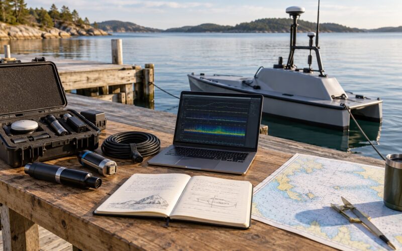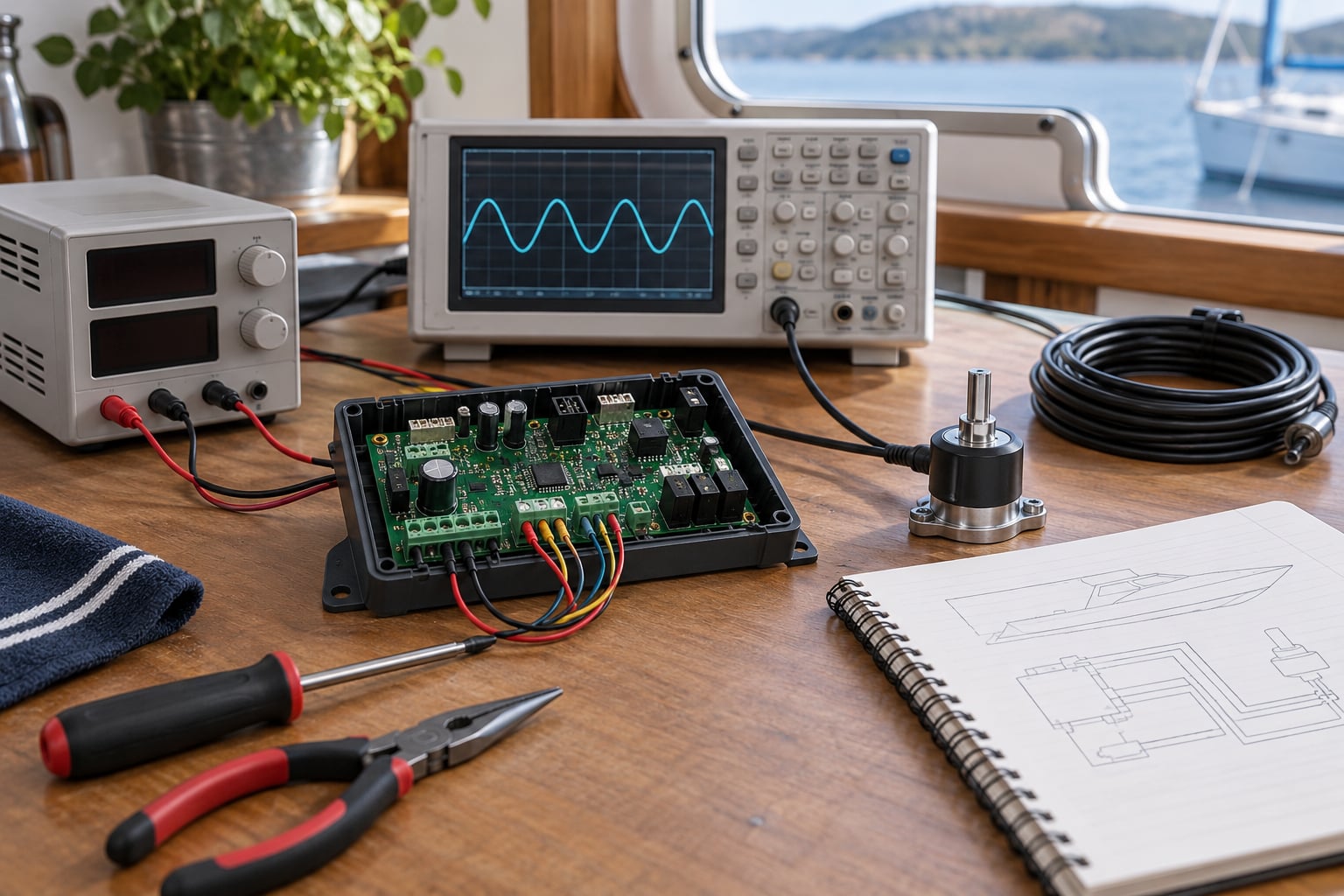
Testing a controller before deployment means proving, on a bench, that the unit powers up cleanly, senses correctly, commands its actuators correctly, and fails safely — before it goes anywhere it cannot easily be reached. A defect found on the bench is a 20-minute fix. The same defect found afloat is a recovery operation, or a lost machine.
The method is a staged gate, not a single test. You climb in fidelity: static and power-on checks, then functional I/O verification, then calibration and drift, then software and fault injection, then a simulated mission, then freshwater and dockside, then a staged sea trial, then sign-off. Each stage has an explicit pass criterion written before the stage starts. If a stage produces no evidence, it did not pass.
Table of Contents
- What You Need
- Step-by-Step
- Define how to test a controller before deployment
- Inspect the hardware and verify power
- Test inputs and outputs with simulated sensors
- Run software, communication, and fault-injection tests
- Repeat the mission in simulation
- Perform controlled freshwater and dockside tests
- Complete a staged deployment trial
- Review evidence and approve deployment
- Common Mistakes
- Frequently Asked Questions
- Conclusion: Make the First Test Safer
What You Need
Here is the equipment list. The first block is what you cannot do without; the second is what makes the difference between a rough check and a real acceptance test.
Essential:
- The controller under test, plus any daughterboards and the firmware you intend to deploy
- A current-limited bench power supply you can set a hard ceiling on
- A multimeter for continuity, supply voltage and current draw at key points
- A way to drive known values into every sensor input — signal generators, resistive dividers, potentiometers, or a pot board
- A way to observe actuator commands — an oscilloscope or logic analyser on the control lines
- A test harness or breakout fixture so you can reach every pin without soldering to the board
- A physical emergency stop that cuts actuator power independently of the firmware
- The project documentation: wiring diagrams, pin map, firmware version, calibration records
Strongly recommended:
- A simulator or loopable sensor source that can replay a wind, compass, GPS, pressure or depth profile
- A test host running the same communication tooling you will use in the field (CAN, RS-485, I2C, Ethernet, radio link)
- Logging or telemetry capture with timestamps, so a failure three minutes into a run is diagnosable
- A plant model — software-only or real-time — for the simulation stage
- Field equipment: a tether and recovery line, a charged spare battery, a handheld radio, and a written abort plan
Do your electrical safety housekeeping first. Bond the supply earth, keep the current limit low until you know what the board draws, disconnect actuators whenever the supply is off, and never work on a live board with the scope ground clip attached unless every point you probe is at true earth potential. A short from a scope probe is a fast way to destroy the thing you were about to test.
Step-by-Step
Define how to test a controller before deployment
Start here, before any hardware is on the bench, because it decides everything that follows. Translate the mission into measurable requirements: correct output for a given input, response time, sensor accuracy, fail-safe behaviour, current limits, communication range, recovery behaviour, and environmental limits.
Write each one as a number with a threshold, not a wish. “Heading holds within 5 degrees in a steady 15-knot breeze” is testable. “Steers well” is not. Then build a test matrix with three columns — bench, simulation, water — and assign every requirement to at least one column. The matrix is also your acceptance record: when the sea trial finishes, you check requirements, not vibes.
Inspect the hardware and verify power
Before power-on, verify polarity on the supply connections, check connectors for correct pin orientation, look for cold solder joints, confirm shielding and grounding are as designed, and check that fuse ratings match what the actuators can draw in a stall.
Power up through the current-limited supply with actuators disconnected. Confirm the expected startup behaviour — indicator states, boot messages, self-test results. Measure supply voltage at the input, at the regulator output, and at the far end of the harness, where droop hides. Measure idle and loaded current and compare against the design figure.
Pass: supply stays inside its specified window at every measurement point, current draw matches the design figure, and the startup self-test completes with no faults. Fail and stop immediately on smoke, a smell of hot plastic, unexpected resets, or any component that gets hot to the touch. Those are defects, not curiosities.
Test inputs and outputs with simulated sensors
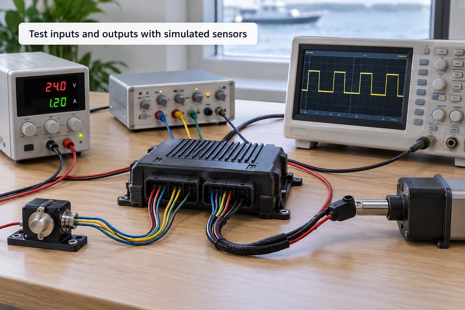
Substitute known inputs for the real sensors. Drive a compass input through a defined sweep of headings, feed a depth sensor a known pressure ramp, present a wind vane a fixed angle. Command each output independently — one actuator at a time, with the rest disabled — and watch the command signal on the scope.
Confirm that sensor changes produce the correct actuator response, and check the edges: the minimum and maximum command, the direction of travel, the rate limit, the deadband, and the shutdown behaviour when the command is withdrawn or the sensor goes out of range.
Pass: every channel responds within its specified range, direction and timing, and out-of-range input produces a defined output rather than an undefined one. Write down the numbers you measured while they are in front of you; you will not remember them in a month.
Run software, communication, and fault-injection tests
Now exercise the logic rather than the wire. Walk the normal operating sequence, then walk the boundaries: minimum and maximum setpoints, step changes, rapid reversals, invalid sensor values like NaN and stuck-at-zero, dropped packets on the bus, two sensors disagreeing with each other, supply voltage sagging under load, an actuator stalling, and a forced reset in the middle of a manoeuvre.
For each injected fault, check that the controller does the defined thing: raises an alarm, logs an event, retries a bounded number of times, degrades to a reduced mode, or commands the fail-safe output. A retry loop with no limit is a defect, not a feature.
Pass: every fault has a defined, bounded, observable response, and the watchdog resets the controller and restores the fail-safe state when software stops responding. Log every anomaly you hit, fix it, then rerun the whole fault set — fixes break other behaviour more often than people expect.
Repeat the mission in simulation
Run the actual mission as a software simulation first: representative routes, waypoint tracking, heading changes, and the disturbances you actually expect — gusts, current, sensor noise, delayed packets. Then move to hardware-in-the-loop, where the real controller hardware drives a simulated plant in real time. That second stage is the one that catches things a pure software model never will: timing jitter, bus behaviour, and thermal behaviour.
Compare waypoint tracking, heading control, energy use, timing, communications and recovery outcomes against the numbers in your test matrix.
Pass: every measured value sits inside its acceptance threshold, and no failure mode appears that the matrix does not already describe. Investigate anything that does before the unit gets near water.
Perform controlled freshwater and dockside tests
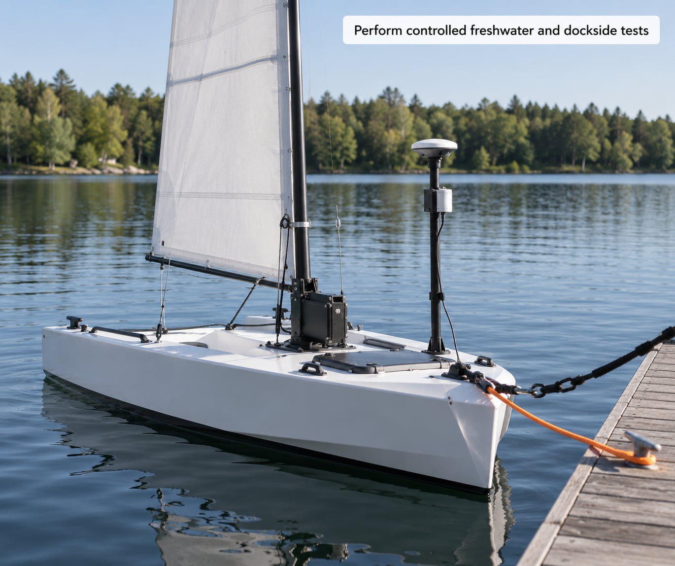
Water introduces everything the bench cannot: sealing, connector corrosion, cooling under load, vibration, radio range over distance, and sensor behaviour with real fluid and real motion. Start alongside the dock with a conservative load and someone ready on the tether.
Verify the emergency stop by pulling it, not by trusting it. Check that the hull seals hold, that connectors stay dry, that temperature inside the enclosure is stable, and that the radio link holds at the range you intend to operate at.
Pass: no ingress, stable enclosure temperature, command link maintained at target range, and the independent stop cuts actuator power immediately. Only then does open water become reasonable.
Complete a staged deployment trial
Begin in calm water with a short route and continuous operator supervision. Do not start with the full mission profile just because the simulation ran it. Compare live telemetry with the expected values from the simulation — the differences are your real-world error budget.
Extend duration and complexity only after defined checkpoints pass. Test manual override and return-to-base deliberately, in the state you would actually need them. Write abort thresholds in advance for wind, current, battery state and communications quality, and treat crossing one as a decision already made, not a discussion.
Pass: every checkpoint met, override and recovery both work on demand, and no abort threshold was crossed.
Review evidence and approve deployment
Archive the test logs, firmware versions, wiring diagrams, calibration records, anomaly list and corrective actions together, in one place, dated. Anyone picking this up in six months should be able to reconstruct what was tested and what the result was.
Require every critical requirement in the matrix to pass. Where something did not pass, either fix it or write down the accepted risk, who accepted it, and what the rollback procedure is. Unattended operation gets its own explicit go or no-go, made by a person, in writing.
Common Mistakes
- Testing only under ideal conditions. Perfect inputs on a quiet bench tell you nothing about fouled sensors or a cold battery. Fix: make the worst realistic case a required test case, not an optional one.
- Skipping fault injection. Normal-operation tests pass on controllers that will fail badly in the field. Fix: budget real hours for fault injection — it is usually the stage where the remaining defects live. Safety tip: run it with actuators on a bench load, not on the real mechanism.
- Trusting a simulator you never validated. A simulator with unrealistic sensor noise and timing tests your imagination. Fix: validate the simulator against one recorded field run before you trust it. Safety tip: a green simulation is evidence, not proof.
- Using an inadequate power supply. A supply that sags under load will manufacture failures that look like firmware bugs and waste days. Fix: use a supply with headroom above your measured peak current. Safety tip: keep the current limit set until you know the real draw.
- Deploying without an independent emergency stop. A software stop is not a stop when the software is the thing that failed. Fix: hardwire an operator-accessible cut that works with the controller unpowered or wedged. Safety tip: test it deliberately, every session.
- Changing hardware without retesting. A swapped connector or a new sensor driver invalidates earlier results. Fix: re-run the affected rows of your matrix and record why they were rerun. Safety tip: treat any hardware change as a new build.
- Judging success without recorded pass/fail criteria. Without thresholds written in advance, every result becomes a judgement call, and judgement calls go the wrong way on a bad day at sea. Fix: write thresholds first, sign the record at the end.
Frequently Asked Questions
How long should a marine controller be soak-tested?
For a sealed enclosure, run the controller under representative load for at least 24 hours continuously while logging enclosure temperature, supply voltage and reset counts, then repeat for 48 to 72 hours before a long unattended deployment. The point of a soak test is to catch temperature-correlated and marginal failures that short runs never reach. If your duty cycle involves submerged operation, add a submerged soak with connectors mated, because corrosion and ingress show up on a timescale no bench run covers.
What sensor accuracy is needed before deployment?
Match required sensor accuracy to what the control loop actually consumes. If heading control holds within 5 degrees, a magnetometer good to 2 degrees is comfortable and one good to 10 degrees will not close the loop. Derive the number from your test matrix: write the control performance target first, work backwards through the loop to the sensor error budget, then verify on the bench against a known reference at several temperatures.
Is a software simulator enough to test an autonomous boat controller?
A software simulator is a good first filter for control logic, route planning and fault handling, and it will save you from testing obvious mistakes on real hardware. It is not enough on its own, because it cannot reproduce bus timing, real sensor noise, thermal behaviour or actuator dynamics. Use it, then move the actual controller into a hardware-in-the-loop rig, and only then to a tethered freshwater test.
Should I use a marine-grade power supply for bench testing?
Not during the bench phase. Use a current-limited laboratory supply so you can see exactly what the controller draws and cap the damage if you have a wiring error. Marine-grade supplies are there for the field, where surge, corrosion and vibration are real. Do check that your bench supply can deliver your measured peak current with headroom, and record the minimum supply voltage the controller tolerates before you assume it is fine.
How much testing does an autonomous sailing robot need before launch?
Enough to fill every row of your test matrix with evidence, and no more than that. In practice that means a full bench and hardware-in-the-loop pass, a fault-injection pass, at least one soak test, a tethered freshwater session, and one supervised sea trial with checkpoints. The matrix tells you when you are done. Skipping a row is fine if you have written down why, and accepted the risk.
Conclusion: Make the First Test Safer
Knowing how to test a controller before deployment comes down to one habit: raising fidelity in stages and refusing to move on until the current stage produces recorded evidence against numbers you wrote down in advance. Bench, then loop, then simulation, then tethered water, then a supervised trial, then sign-off. Every stage catches a class of defect the previous one cannot.
Start today by converting your mission requirements into a test matrix with explicit pass, fail and abort criteria. Fill in the first row before you switch anything on.