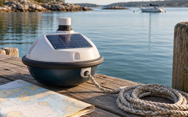
Learning how to build a wave buoy comes down to four jobs: a float that follows the water surface, a sensor that measures that motion, electronics that survive salt water, and firmware that turns raw motion into numbers you can actually use. A commercial wave buoy runs into the thousands of dollars plus service costs, which is why most coastal monitoring data comes from a small number of well-funded stations.
A home build trades absolute accuracy for access. You will not match a national network station, but you can get usable significant wave height, peak period and swell direction for a surf spot, a harbour mouth or a wave energy project. This guide walks the whole build in order, from choosing a sensing method to validating your first deployment against a known reference.
Budget a weekend for the tank build and a few evenings for electronics and firmware. Salt water is the hard part, not the code.
Table of Contents
What You Need
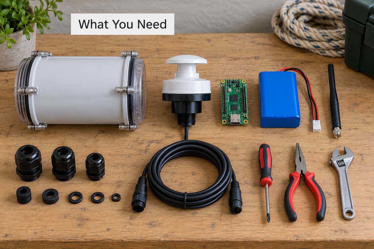
A wave buoy build needs five categories of material: the float, the sensor, the electronics, the power system and the recovery gear. Here is what each group has to do and what to pick when you are starting out.
Float and ballast
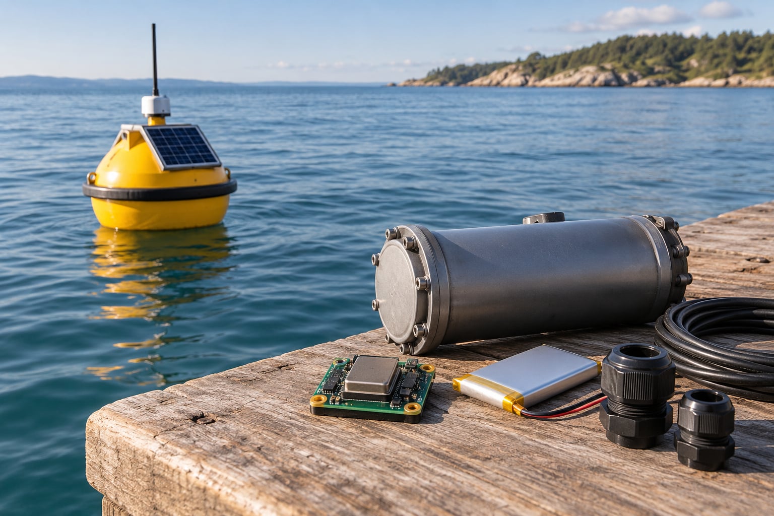
Closed-cell marine foam is the standard choice because it does not absorb water the way expanded polystyrene does. A solid PVC or HDPE tube works too, and for a first tank build a foam block in a sealed plastic tub is enough to prove the concept. Add ballast underneath so the buoy sits upright instead of lying on its side, and keep enough freeboard that a big wave never buries the hull.
Sensor and controller
For wave height and period, a six-axis inertial measurement unit is the cheapest route. For surface elevation measured directly, plus position and drift tracking, add a GPS receiver. Add a magnetometer only when you need wave direction, and keep it away from the battery, the antenna and any steel fasteners. An ESP32 or a similar low-power board covers sampling, storage and radio in one package; a Raspberry Pi is fine for a tethered prototype but draws far too much power for a drifting buoy.
Enclosure, seals and cabling
Use a cylindrical electronics canister with a screw-on or clamped lid, marine-grade cable glands and heat shrink on every joint. Conformal coating on the boards plus a potting layer of epoxy or polyurethane inside the canister is the difference between a buoy that survives and one that comes back full of seawater.
Power and telemetry
A lithium cell with a low self-discharge chemistry keeps the electronics asleep between readings without draining fast. Saltwater-rated solar panels extend a deployment from months to a season. For shore-based work, LoRa or WiFi is enough; for anything past radio horizon, an Iridium satellite modem is the standard open-hardware answer, and its airtime cost is worth budgeting before you commit.
Data storage and recovery
Always carry a microSD card, even with telemetry. A buoy that transmits every thirty minutes and stores everything between transmissions will not lose a storm record to a single dropped session. Add a surface float marker, a retrieval line and a small waterproof bag for the spare electronics so recovery is not a guessing game.
How to Build a Wave Buoy Step by Step
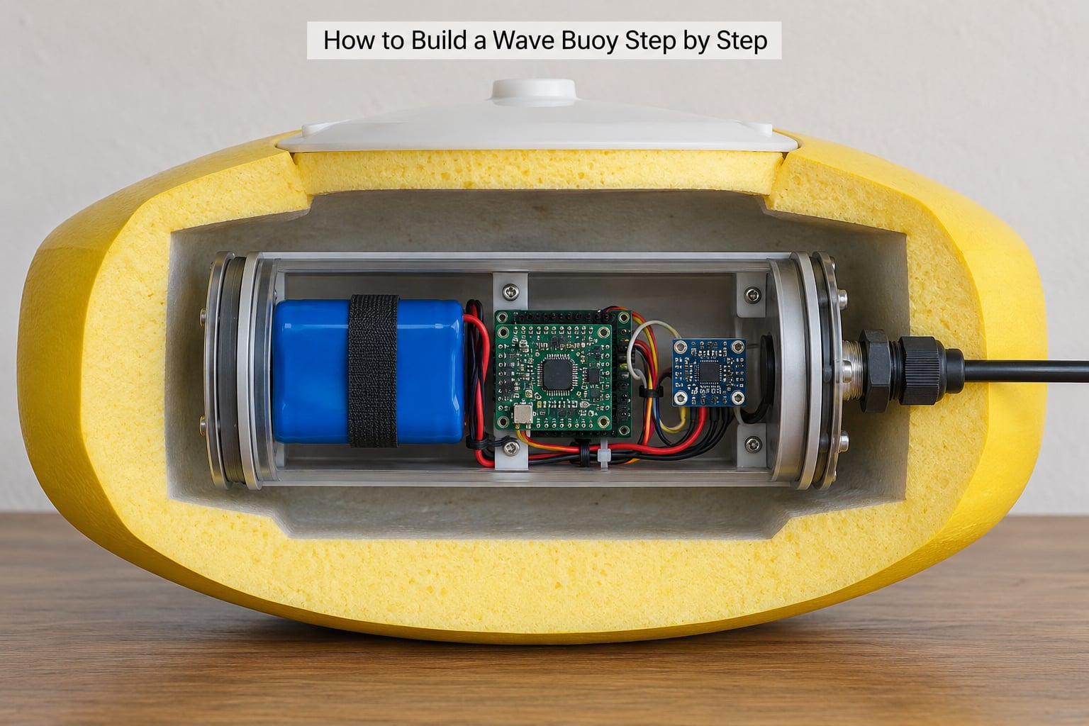
The sequence below runs from deciding what you are measuring all the way to data you trust. Each stage has a success check, and if the check fails you stop there rather than carrying a hidden fault into the water.
Choose the Measurement and Power Budget for Your DIY Wave Buoy
Decide first whether you want wave height alone, wave height with period, or full direction as well. Each addition costs power, and power decides how long the buoy survives. Sample the accelerometer at roughly 2.5 times per second: that is the rate national systems use for surface-following buoys, and it comfortably covers wave periods down to a couple of seconds without wasting current.
Now do the arithmetic. If the controller draws about 20 mA while sampling and the radio bursts at 150 mA for a short window every thirty minutes, a 1000 mAh cell gives you a season of intermittent data rather than months of continuous data. Write the duty cycle down before you solder anything, and keep parts asleep whenever they are not needed.
Success check: you can state the sample rate, the transmission window and the expected life in weeks on one sheet of paper. If you cannot, the design is not finished yet.
Fabricate and Waterproof the Buoy
Shape the float so its waterline sits low enough to follow the surface and high enough that it never ducks under. A low freeboard improves response but floods the hull in steep seas; a high freeboard survives waves but stops tracking the surface and turns your measurements into noise. Aim for a hull that stays upright on its own, with ballast low and the electronics canister mounted low and centred.
Mount the canister mechanically rather than with glue alone, so vibration does not work the seals loose. Run every cable through a gland, strain-relieve it inside the canister and keep connectors away from the waterline. Vent the canister with a hydrophobic membrane if you can, because a sealed air volume will pump moisture into the boards as temperature swings through the night.
Success check: the float sits upright in a bathtub for an hour with no list, and the sealed canister submerged for twenty-four hours keeps its interior dry on an absorbent wipe test.
Assemble the Sensors and Data Logger
Mount the inertial measurement unit rigidly and in a known orientation. An IMU that flexes or sits at an angle produces a tilt bias that looks exactly like a long-period wave, and you will spend a weekend chasing a problem that is really three degrees of misalignment. Fix the board to a plate, not to the foam, and record which axis points up.
Wire the sensor, the controller, the microSD card and the power regulation on a short harness. Add a decoupling capacitor at the sensor, keep the accelerometer wiring away from the radio antenna lead, and star your ground returns at the battery negative. Fit a battery monitor divider so you can log voltage and catch a failing cell before it silences the buoy.
Success check: on the bench, tap the hull gently and the logged signal shows a clean impulse with no high-frequency chatter that never settles.
Add Wireless or Local Logging
Start with local logging. The buoy writes a timestamped binary or CSV line every sample, flushes to the card, and closes the file cleanly at each transmission window. Written this way, a power cut costs you one window, not the whole deployment.
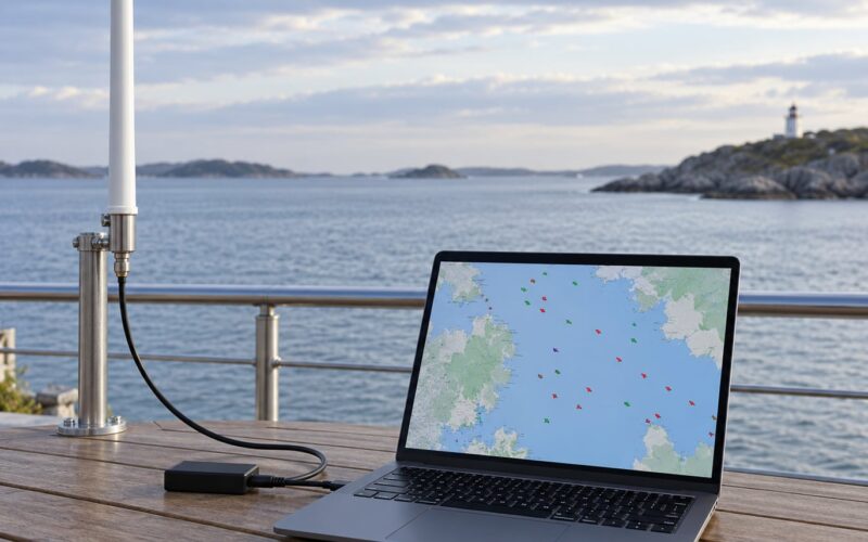
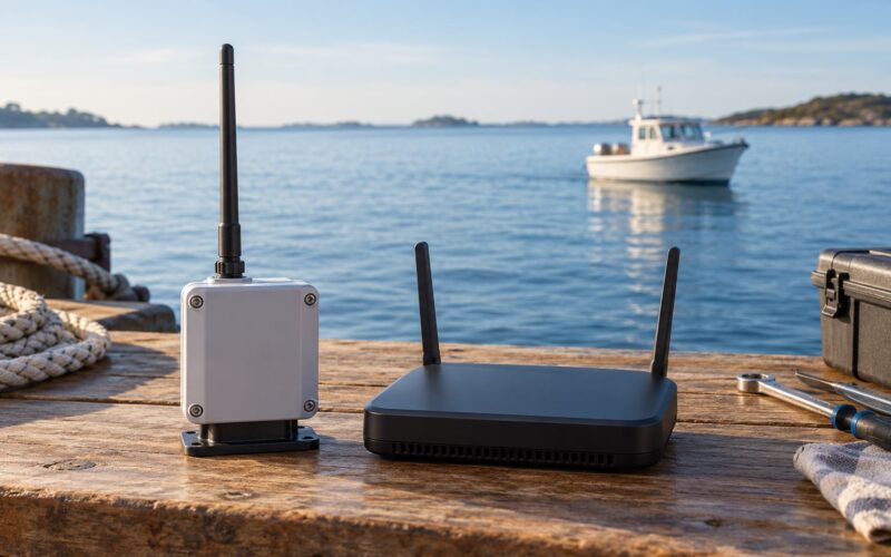
Then add telemetry if you need it. LoRa or WiFi covers a harbour, lake or short stretch of coast and costs nothing to transmit. An Iridium modem is the right call for anything past radio horizon, and it changes the design: transmission takes seconds, not milliseconds, so set a real timeout, retry a limited number of times and fall back to the card instead of hanging the sampling loop. Expect a few kilometres for LoRa in a cluttered coastal site and global coverage from satellite, both far shorter than people assume when the antenna sits low on a floating object.
Success check: the buoy completes a full transmit-and-recover cycle indoors, and a deliberately cut antenna produces stored data rather than a frozen logger.
Write and Test the Sampling Firmware
The firmware has a few jobs and no room for drama. On wake, read the timestamp, take the accelerometer burst, downsample into a fixed-rate window, append to the file, check the battery, then sleep until the next window. Keep the loop tight, keep the timing derived from a real clock rather than a delay, and write an error flag whenever a read fails.
Filter out gravity with a high-pass filter before you store the data, otherwise your spectrum fills up with a large zero-frequency peak that swamps the waves. Log raw and filtered values during bring-up, then decide later which you keep. Do the analysis on your computer, not on the buoy: pull the file, run a Fast Fourier Transform over a thirty-minute window, integrate the energy spectrum to get significant wave height as four times the square root of the zeroth moment, and read the peak period off the tallest spectral peak.
Success check: a hand-shaken unit on the desk produces a file where the dominant period matches roughly the period you shook it at.
Calibrate, Deploy, and Validate the Measurements
Start with a controlled tank. A wave paddle, a length of hose oscillating on a beam, or even a person moving a tray of water can produce a surface elevation you know. Shake the buoy through a known range of heights, plot accelerometer output against true displacement and derive the transfer function and response factor you will use to convert acceleration into elevation.
Then test in protected water, a cove or an estuary, with a second reference nearby: a pressure sensor on a fixed pole, a phone GPS logger on a known point, or an existing public station network. Deploy tethered before you deploy drifting, and log your corrections in a written calibration record rather than in your head. If your values sit consistently low or high, adjust the response factor and note why.
Success check: your significant wave height agrees with the reference within a margin you can state out loud, and you know which direction the error goes in bad weather.
Common Mistakes
Most failed wave buoy builds are not electronics failures. They are water, noise or unverified data, and every one of them has a straightforward fix.
- Leaking enclosures. The default mistake is a scavenged container closed with tape. Use a purpose-made canister with clamped seals and cable glands, then do the bathtub test before anything else.
- Foam that soaks up water. Open-cell foam gains buoyancy loss over a season. Closed-cell marine foam or a solid shell keeps its properties, and a float that stays light stays responsive.
- Unstable float behaviour. Ballast too high, a canopy catching wind, or a canister mounted off-centre will make the hull roll and rock. Heave is the motion you want; rocking contaminates everything downstream.
- Spectral aliasing. Sampling slower than twice the highest frequency of interest folds high-frequency energy back into the band as fake waves. Sample faster, then filter deliberately, rather than discovering the alias later.
- Noisy readings. Radio interference, a magnetometer near the electronics and an unfiltered gravity offset all produce motion that is not a wave. Separate the antenna from the sensor harness, orient the magnetometer away from steel, and high-pass the stored data.
- Flat batteries. Size the cell for the transmission duty cycle, not the average current draw. Log voltage every cycle and reduce sample rate before you cut telemetry.
- Unverified data. A buoy that produces numbers nobody has checked will eventually produce a wrong number with confidence. Compare against a public station or a pole-mounted pressure sensor before you publish or rely on it.
- Mooring chafe and biofouling. Tethered buoys need a chafe guard where the line meets hardware, and hull growth changes drag and response. Inspect at every retrieval and log your cleaning intervals.
One more habit pays for itself: keep a written log of every deployment, calibration and failure. Ocean data is worthless without the conditions it was collected in.
Frequently Asked Questions
What is the simplest way to build a wave buoy?
The simplest version is a closed-cell foam float carrying a sealed electronics canister with one microcontroller, a six-axis IMU, a microSD card and a lithium cell. Skip telemetry and solar on the first build, log to memory, retrieve the buoy by hand and analyze the file in Python. You can have real wave data in a weekend of work.
Can a DIY wave buoy measure wave height accurately?
Not to the standard of a national station, but a careful home build can land within roughly 10 to 20 percent of true significant wave height once its response factor is calibrated against known conditions. GPS-based buoys track the surface directly, while accelerometer buoys need a transfer function to convert acceleration into elevation. A written calibration record matters more than the parts list.
Which sensors should I use for a low-cost wave buoy?
Start with a six-axis IMU and a temperature sensor, which is enough for wave height and period. Add a magnetometer only if you need direction, and position it away from the battery and the electronics you have potted into the same canister. GPS adds position, drift tracking and a direct surface elevation signal, at a noticeable cost in power.
How long can a small wave buoy operate on one battery?
A 500 to 1000 mAh lithium cell with duty-cycled sampling and periodic transmission usually runs several months. Sampling rather than transmission dominates the budget, so shorten the accelerometer duty cycle first and keep the GPS off except when you need a fix. A saltwater-rated solar panel above the spray line can stretch that to a full season.
Do I need a GPS module for a wave buoy?
No, GPS is one of two ways to sense waves. With GPS, the buoy derives surface elevation from its own position fixes and gains drift tracking as a bonus. With an accelerometer, it infers motion without satellites and keeps logging in a bay with a poor sky view. Choose based on power, cost and whether you need to know where the buoy has drifted.
Is it safe to deploy a DIY wave buoy in the ocean?
Deploy into a sheltered cove or estuary first rather than straight into open water. Fit a bright surface marker and a retrieval line, keep clear of channels and mooring fields, and tell someone onshore when you expect the buoy back. A drifting buoy also needs a drift forecast, an expiry plan and a decision about what happens if it cannot be recovered.
Conclusion
If you want to learn how to build a wave buoy, start smaller than the ocean: foam float, sealed canister, one inertial sensor, a memory card and a tank with a wave paddle. Prove the measurement chain in a bathtub before you trust it in a swell.
Then add the parts that make it useful — telemetry, solar power, a magnetometer for direction — one at a time, keeping a calibration record and a controlled test for each change. That sequence is how you build a wave buoy whose numbers you can defend, not just collect.