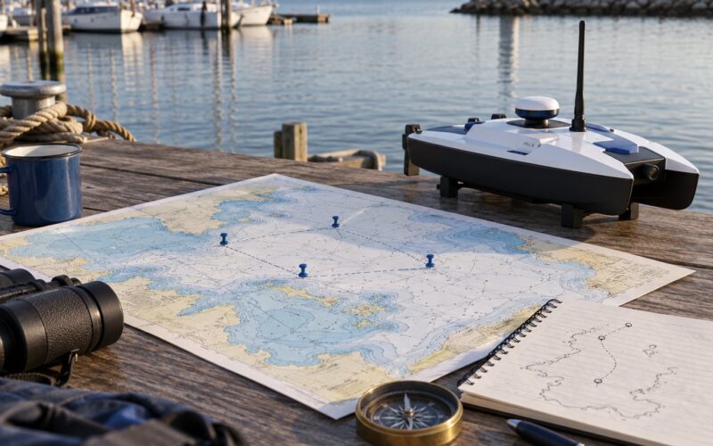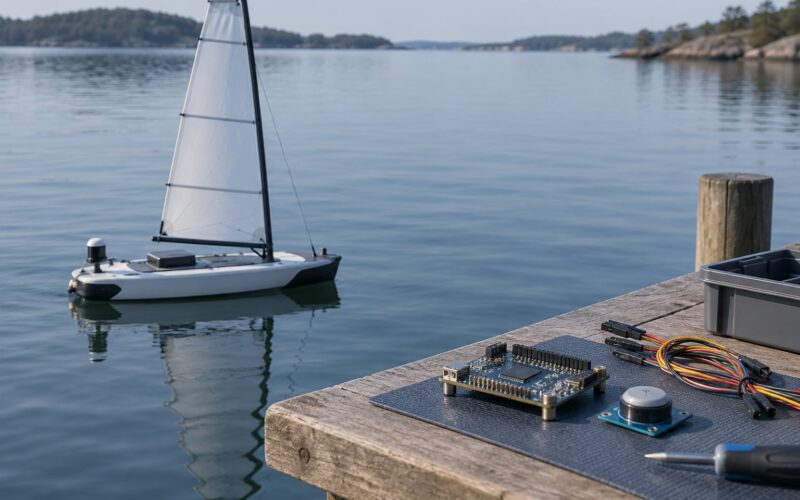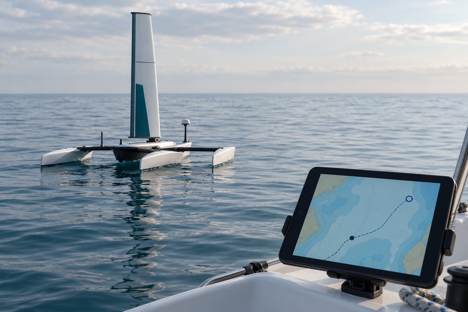
A waypoint is a stored coordinate with attributes attached, not a steering command. Waypoint navigation is the control loop that repeatedly steers a vessel toward the active waypoint, declares arrival once the vessel is inside that waypoint’s radius, promotes the next point in the list, and repeats until the sequence ends. On a sailing robot the loop has to close on a boat that cannot slow down on command and cannot point wherever it likes.
That last constraint is what separates a sailing robot from a cart on rails. A wheeled robot can stop, spin and go anywhere in its plane. A sailboat has momentum, one dominant control surface at the helm, and a course that only goes well when the wind allows it. Everything below is about how the loop is built to live with those facts.
Reviewed for 2026. Everything here describes how an open-source sailing robot at Protei handles a route, and the same loop appears in any platform that follows a coordinate list.
Key takeaways
- Waypoint navigation is a repeated sense, decide, act loop, not a single calculation.
- The active track leg is the line between the last waypoint and the next one, and cross-track error is the perpendicular distance from the vessel to that line.
- Arrival radius is a design choice. Make it larger than the expected cross-track error, the fix tolerance of the GPS and the turn radius of the hull.
- Guidance picks the target. Control turns that target into rudder angle. Keeping the two layers separate is what makes the loop debuggable.
- Current and leeway do not average out. They push the vessel sideways for the whole leg, so the correction happens continuously.
- Test in simulation, then in protected water, with waypoints close enough together that a bad turn is recoverable.
Table of Contents
- What Is Waypoint Navigation?
- How Waypoint Navigation Works on a Sailing Robot
- The Waypoint Navigation Loop Step by Step
- How the Robot Knows Where It Is
- How a Sailing Robot Decides What to Do Next
- How the Robot Reaches and Leaves Each Waypoint
- How Waypoint Navigation Handles Wind, Currents, and Course Correction
- What Data a Waypoint Navigation System Needs
- How Waypoint Failures and Safety Rules Are Handled
- How to Test Waypoint Navigation Safely
- Frequently Asked Questions
- How accurate does GPS need to be for waypoint navigation?
- How far apart should waypoints be on an autonomous sailing robot?
- Can a sailing robot follow waypoints using wind alone?
- What is the difference between waypoint navigation and path following?
- Should waypoint navigation be tested in simulation before going on the water?
- What should a sailing robot do if its GPS position is lost?
- Conclusion
What Is Waypoint Navigation?
Waypoint navigation is following an ordered list of geographic positions without a person at the controls. Each point in the list is a waypoint: a latitude, a longitude, and a set of attributes that tell the platform what to do when it gets there.
A waypoint is data, not an instruction. It does not say turn to port or ease the sheet. It says be here, within this many metres, by this time, and then do this thing. The steering between waypoints is computed continuously by the controller, and that is where the platform-specific work happens.
What a single waypoint stores
- Latitude and longitude. The position itself, usually stored in decimal degrees to at least six decimal places. Six decimals is roughly 0.1 metre of resolution, which is far finer than any consumer receiver resolves in practice.
- Name or ID. So the log, the display and the operator can all refer to the same point.
- Arrival radius. The distance at which the waypoint counts as reached. Typical values run from 5 m for a survey vessel holding a line to 50 m or more for a small boat at low speed.
- Target speed. A speed cap for the leg leading into this point, often as a fraction of the vessel maximum.
- Hold time or action. Linger for a set period, sample data, deploy, drop a mark, or loiter until released.
- Optional arrival heading. Some systems let you specify the course to be on when you arrive, which matters when a sailboat wants to arrive bow-to-wind rather than beam-on.
Waypoint, track and route are not the same thing
A waypoint is a point. A track is an ordered list of points plus the legs between them. A route is the whole mission, which may include several tracks, holds, abort points and behaviour rules at the end. Many devices use the words interchangeably, which is why operator manuals sometimes feel contradictory.
The distinction matters when something goes wrong. If the robot missed a waypoint, you need to know whether the problem is the point, the leg, or the mission logic that chose to skip it.
How it differs from the alternatives
Continuous path following hands the controller a dense curve or line and asks it to track the path everywhere, not just at discrete points. Waypoint following is the coarser cousin: fewer decisions, less data, easier to author by hand and easier to debug from a log.
Remote control puts a human in the loop for every correction. It works on a calm afternoon and fails the moment the boat is out of sight or the channel drops out. Waypoint navigation keeps the loop running when the link is gone, which is the whole reason to build it.
Single-goal go-to is waypoint following with a list length of one. It is genuinely useful and it is what most people mean when they say the robot can navigate. It also does not exercise sequencing, arrival rules or end-of-route behaviour, so it hides a surprising number of bugs.
How Waypoint Navigation Works on a Sailing Robot
How waypoint navigation works on a sailing robot comes down to one loop that runs several times a second: estimate where the boat is, compare that to the active leg, decide which heading closes the gap, move the rudder, then repeat with fresh data.
Underneath that loop sit four layers, and the value of separating them is that each one fails differently.
- Mission plan. The waypoint list, arrival radii, hold times and end-of-route behaviour. Static data, loaded before departure.
- Guidance. Decides which waypoint is active and what the target heading should be. It knows about geometry and wind feasibility, not about rudder angles.
- Control. Turns the target heading into a rudder command, typically a proportional-integral-derivative structure acting on heading error.
- Actuation and sensing. The sail servo or winch, the rudder actuator, the rudder position feedback, the GPS and the compass.
The layering is what lets you diagnose a fault. If the robot is holding the wrong heading perfectly, guidance is at fault. If the heading is right but the boat is crabbing sideways, that is current and leeway, which is physics, not a software bug.
On a sailing robot, guidance is harder than on a motorised platform because the achievable headings are a function of wind direction. A route leg pointing dead upwind simply cannot be steered. The guidance layer has to know that, which is why wind data is not optional here in the way it is on a car.
The Waypoint Navigation Loop Step by Step
The loop has six steps and it never pauses. Here is the full sequence from the moment a mission is loaded to the moment it completes.
- Load and validate the mission. Parse the waypoint list, check for duplicate points, zero-length legs and gaps between consecutive coordinates, and assign an arrival radius to anything that lacks one. Refuse to arm if a leg is impossible or the list is empty.
- Project the coordinates into a local frame. Convert the latitude and longitude of every waypoint into flat metres relative to a reference point near the boat. Working in degrees makes distance maths awkward; working in metres relative to a tangent plane makes it trivial.
- Estimate the vessel state. Take a GPS fix for position, a compass reading for heading, and derive speed and course over ground from the change in position between fixes. A rudder angle reading comes from the feedback unit if one is fitted.
- Compute the error on the active leg. Work out the bearing to the next waypoint, the along-track distance remaining, and the cross-track error, which is the signed perpendicular distance from the vessel to the line joining the last waypoint to the next.
- Decide a target heading and act on it. Offset the bearing to the waypoint by an angle proportional to the cross-track error, then hand that target to the controller, which drives the rudder toward it. The sail is trimmed separately against the apparent wind.
- Test for arrival and advance. When the distance to the active waypoint falls inside its arrival radius, or the along-track distance passes the point, mark it arrived, run its hold or action, and promote the next waypoint. Repeat from step 3.
Where the loop ends
On the final waypoint the behaviour is a decision, not a default. Common endings are: hold position at the last point until released, return to the first waypoint and run the route again, or proceed directly home. Whichever you pick, encode it explicitly. A robot that stops dead with the sails still drawing is a robot that has to be recovered manually.
A worked leg
Last waypoint is at 0,0 in the local frame. Next waypoint is 400 m east at 400,0. The boat’s actual position is 180,14. Along-track distance is 220 m. Cross-track error is 14 m to starboard of the leg, so the sign is positive on that side and the guidance layer needs to bias the target heading to port to pull back.
With a cross-track gain of 3 degrees per metre of error, the target heading sits 42 degrees to port of due east, which is 102 degrees true in that leg. The controller works the heading error from there, and the loop repeats on the next position fix.
How the Robot Knows Where It Is
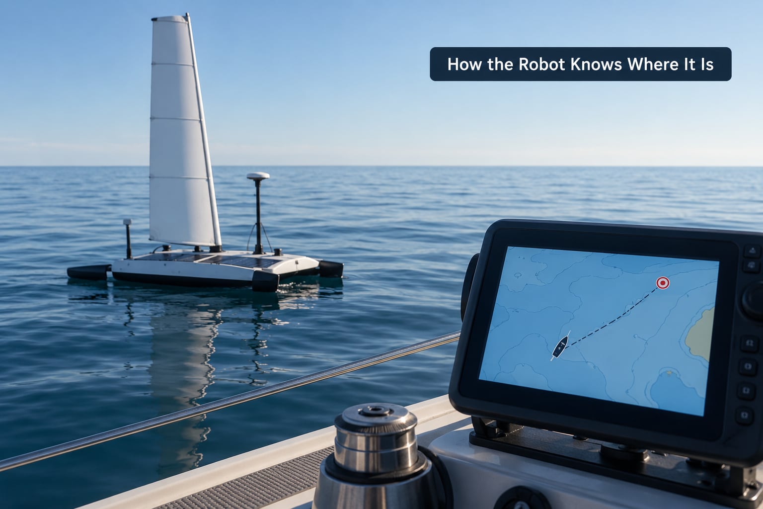
Position comes from a GNSS receiver, and it is the only input in the loop that cannot be inferred. Everything else can be estimated; the absolute position has to be measured.
The practical problem is not resolution, it is error. A receiver may report a position to a metre, but the actual error on a small boat near a shore structure can be 10 m or more, and that number changes with the sea state and the surroundings.
| Error source | Typical magnitude | What it does to the loop |
|---|---|---|
| Horizontal accuracy (open water) | 2 to 5 m | Sets the floor on cross-track error that no amount of steering can remove |
| Satellite geometry (poor constellation) | 5 to 15 m | Error grows in steps and the fix quality figure changes without warning |
| Multipath near a hull, mast or cliff | 5 to 30 m, biased | Pushes position consistently to one side, so the robot holds a false line |
| Update rate | 1 Hz common, 5 to 10 Hz on high-rate receivers | At 1 Hz and 3 knots the boat moves 1.5 m between fixes, which sets the fastest observable correction |
| Latency (fix to usable output) | 100 to 1000 ms | Adds phase lag to a heading correction and makes fast turns overshoot |
| Coordinate projection error | Under 1 m over a few kilometres | Negligible when the frame origin is near the vessel, serious when it is fixed at the start of a long mission |
The multipath row is the one that costs people real time. A systematic bias does not average out, because the loop keeps correcting toward a position that is not where the boat is. If the boat appears to hold a line 8 m to port of the plotted track on every leg in the same direction, suspect the antenna installation or the surroundings before you suspect the controller.
Log the receiver’s reported accuracy and fix quality alongside every position. A controller that can see the quality figure can raise the arrival radius or refuse a turn when the fix degrades. A controller that cannot will sail confidently into the error.
How Position, Heading, Wind, and Speed Inputs Work Together
Position alone tells the loop where the boat is but not which way it is pointing, and heading alone says nothing about where the boat has drifted. The two together produce the pair of numbers that matter most: course over ground and speed over ground.
Compare heading to course over ground and the difference is the crab angle, which is the sum of wind leeway and current set acting on the hull. On a close reach in 15 knots of breeze, 3 to 5 degrees of leeway is normal. Push that through a loop with proportional gain and it becomes a standing offset that the controller has to fight the whole leg.
Wind direction is what converts a desired heading into an achievable one. Apparent wind angle gives the sail something to work with, and the trimmer sets sheet tension from it. The rudder is left to handle the small corrections, because a sailing robot that tries to steer to a waypoint by changing sail position alone is slow and loses efficiency constantly.
How a Sailing Robot Decides What to Do Next
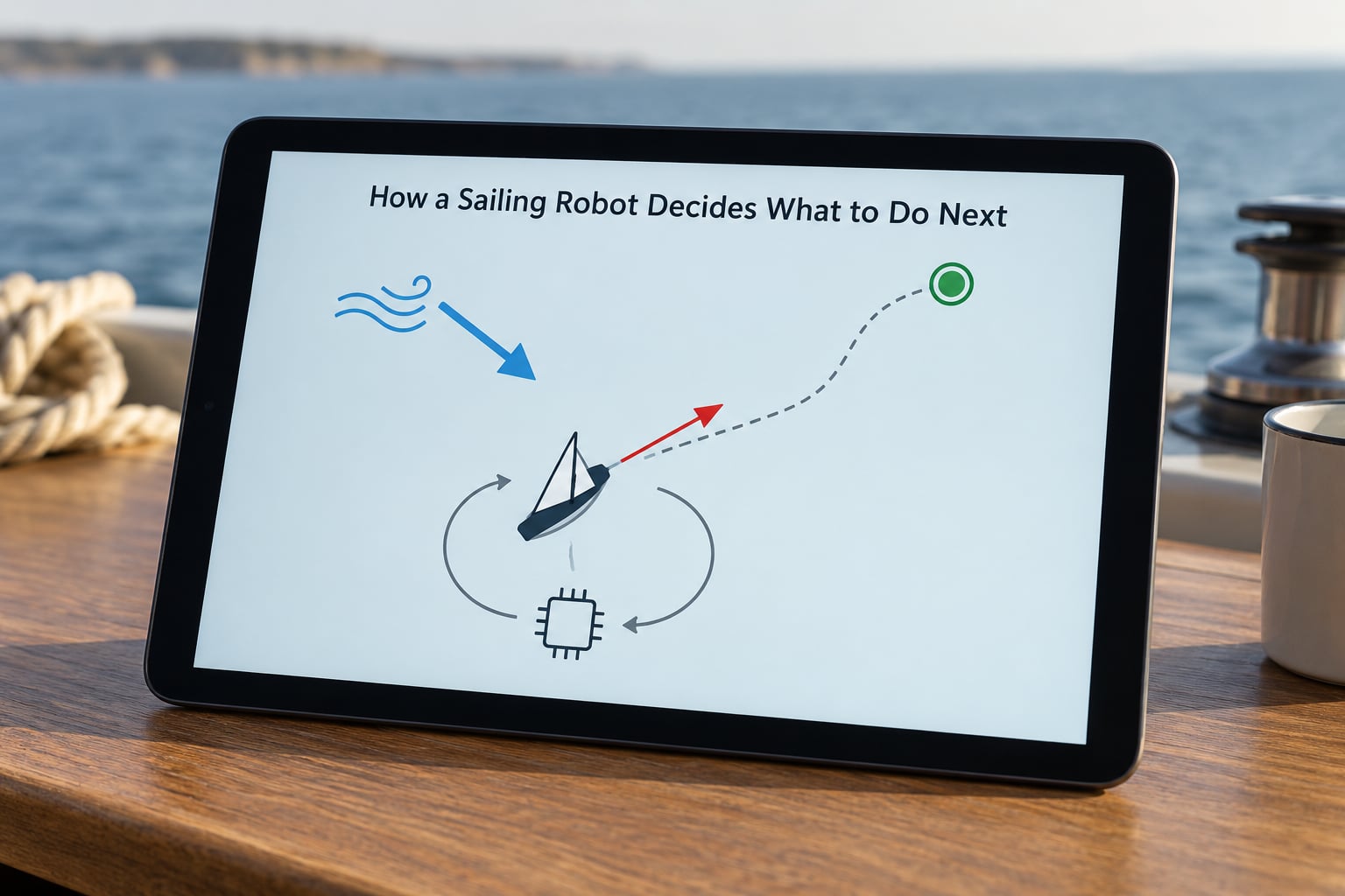
The guidance layer picks the target and works out the heading that would close the gap. The control layer converts that heading into a rudder command. Splitting them is what makes a sailing robot debuggable.
Guidance asks two questions. Which waypoint is active, and given the wind right now, is a course toward it achievable? If the answer is no, guidance does not push the heading controller against its limits. It either asks for a course change upwind, tacking to build speed before committing, or falls back to a slower, more achievable approach angle.
Control asks one question: given a target heading, where should the rudder be right now? A proportional-integral-derivative structure answers it from three terms. The proportional term reacts to heading error. The integral term removes a standing offset, which is what kills the constant crab caused by wind and current. The derivative term damps the response so the boat does not swing past and come back.
One term does most of the visible work on a sailboat. Rudder gain, which is the proportional term, has to be matched to the boat’s inertia: a displacement hull with a full keel needs a lower gain than a light planing dinghy, because the same rudder angle changes the rate of turn more slowly.
The integral term is the one that gets people into trouble. Wound up too aggressively while the boat is stuck head to wind or blocked by current, it saturates, and when the obstruction clears the boat snaps around. Most systems therefore clamp the integral, and it is worth knowing what the clamp is.
On an autonomous sailing robot the guidance layer also owns one more decision that a car never faces: whether the sail or the rudder should absorb the correction. Sailing toward the target with the wrong sail trim costs speed, not safety, so it is often better to leave sail trim to the wind vane and let the rudder handle everything from the helm aft.
How the Robot Reaches and Leaves Each Waypoint
Arrival is a geometric test against the active waypoint, and how you write that test decides whether the robot turns neatly or cuts the corner.
The bearing from the boat to the active waypoint, corrected by an angle proportional to the cross-track error, gives the target heading. That is the whole steering law for most implementations, and it works because the correction term decays naturally as the cross-track error shrinks.
Four numbers that describe the leg
- Bearing to waypoint. The straight-line direction from the vessel to the next point.
- Along-track distance. Distance projected onto the leg direction, which is what decreases as you sail the leg.
- Cross-track error. The signed perpendicular offset from the leg. Signed, because which side of the line you are on decides which way to correct.
- Distance to waypoint. The straight-line range, which is what the arrival test usually uses.
Sizing the arrival radius
The arrival radius must be at least as large as the steady-state cross-track error the loop settles at, plus a margin for GPS error and one for turning. If the controller holds a 6 m offset on a long leg in current, a 5 m radius means the robot may never trigger arrival and will sail straight past the point.
Four criteria set it in practice. Take the expected cross-track error from a logged transect and double it. Add the reported GPS accuracy at the site. Add half the hull’s turn radius if the next leg is a hard turn, so the vessel is already swinging when it commits. And keep the total under whatever distance the next leg needs to straighten out, or the robot spends its whole leg recovering from the last turn.
Lookahead and why spacing matters
Some controllers start aiming at a point projected along the leg, some metres ahead, rather than at the waypoint itself. Lookahead damps the response near the waypoint, where the bearing changes fast and a naive loop oscillates.
Waypoint spacing sets how hard the robot has to turn. Short legs mean frequent small corrections and tight radius turns, which a sailboat under sail cannot make well. Long legs mean a long time accumulating cross-track error before anyone looks at the log. Somewhere between a few hundred metres and a kilometre suits a typical small autonomous sailing robot in moderate conditions.
Very tight sequences, the kind generated automatically for an indoor robot in a research paper, need steering that can stop and pivot. A sailboat cannot do either. That is the sim-to-real gap in one sentence, and it is why an algorithm that scores well on a grid of indoor waypoints often cuts corners badly on water.
How Waypoint Navigation Handles Wind, Currents, and Course Correction
The loop corrects continuously rather than in one correction per leg. The boat never sails the leg in a straight line; it sails it in a shallow S that averages out to the line.
Wind matters twice. It sets the achievable headings, so guidance must respect it, and it pushes the hull sideways, so control must trim out the resulting leeway angle. The second effect is small in magnitude, a few degrees, and entirely persistent.
Current matters as set and drift. Set is the direction the water is going, drift is how fast. A boat steering a fixed heading across a 1 knot current set at 90 degrees accumulates roughly 0.9 m of cross-track error per minute of sailing. Over a 20-minute leg that is 18 m, which is larger than most arrival radii on a small platform.
A numeric example
Leg length 2 km, boat speed over ground 3 knots, current set 90 degrees to the right of the intended track at 1 knot. The lateral component of the current is 1 knot, so the loop must hold about 5 degrees of heading offset for the whole leg to keep the cross-track error near zero.
At 3 knots the leg takes 22 minutes. If the controller corrects once every 30 seconds rather than continuously, error builds between fixes and is only removed at the next update, so the practical settling error is a few metres rather than zero. Now set the arrival radius at 15 m and the robot has a workable margin. Set it at 3 m and it will frequently sail past a waypoint it has already crossed in projection.
Tacking and gybing enter when the required course is outside the achievable band around the wind. A guidance layer that knows the apparent wind angle will tack to build speed when the target lies upwind of the no-go zone, then gybe back once the target falls inside it. A guidance layer that ignores wind will simply sit head to wind, sails luffing, making no progress and burning battery.
Dead reckoning and its limits
Between fixes the controller can propagate position from heading and speed through water, and that is genuinely useful for a few seconds when a fix is late. It is not a substitute over minutes. Propagated position drifts as heading error integrates into cross-track error, and on a sailboat the leeway angle is not known exactly, so the propagation error grows in an unknown direction.
What Data a Waypoint Navigation System Needs
Three inputs are essential: position, heading and the mission plan. Everything else either improves accuracy or lets the system recognise that it is lost.
| Input | Priority | Role in the loop |
|---|---|---|
| Latitude and longitude | Essential | Absolute position; the only ground truth in the loop |
| Heading from a compass | Essential | Closes the loop; position alone cannot steer a boat |
| Mission plan | Essential | The waypoint list, radii, holds and end behaviour |
| Speed over ground | Useful | Waypoint filtering, timeout logic, arrival sanity checks |
| Course over ground | Useful | Crab angle, drift detection, compass fault detection |
| Apparent wind angle | Essential on sail | Feasibility of the requested course and sail trim |
| True wind speed and direction | Useful | Predicting where the achievable band will be in ten minutes |
| Rudder angle feedback | Useful | Detects a stalled drive, a fouled blade or hunting |
| GNSS fix quality and satellites used | Useful | Widen the arrival radius or refuse a turn when the fix degrades |
| Actuator command echo | Useful | Confirms the command left the controller, separates software from hardware faults |
| Leeway estimate | Optional | Lets the controller pre-compensate instead of correcting after the fact |
| Depth or obstacle return | Optional | Turns a planned route into a checked one in shallow or busy water |
The compass deserves a note because it is the sensor most often blamed unfairly. A fluxgate compass measures the earth field and is disturbed by steel, electronics and the boat’s own motor current. A rate gyro measures turn rate and drifts. Many systems run both and fuse them, because neither is trustworthy alone on a small steel-hulled boat.
Waypoints themselves arrive over a link, and the format matters more than people expect. Marine systems typically use NMEA 2000 sentences carrying a sentence identifier for each waypoint. Small robotics platforms often use MAVLink mission items or a ROS 2 route topic. Check that the receiver’s own storage limit and upload method are understood before designing a mission longer than a handful of points.
How Waypoint Failures and Safety Rules Are Handled
A waypoint system fails in predictable ways, and each failure has a detection signal and a safe response. The detection is the part people skip, and it is the part that matters.
| Failure | How it shows up | Safe response |
|---|---|---|
| Stale or lost GNSS fix | No new fix past the expected interval; speed over ground drops to zero while heading is steady | Stop advancing the sequence, hold or return to the last known good waypoint |
| Compass fault | Course over ground diverges from heading by more than the plausible leeway angle | Fall back to heading hold with reduced confidence, or surface and abort |
| Compass deviation near steel | Constant offset in the same area, correct after leaving it | Recalibrate on departure, log the calibration time |
| Missed waypoint | Range starts increasing again without arrival triggering | Suppress the arrival until the robot returns inside the radius, with a timeout |
| Crossed track | Signed cross-track error flips sign repeatedly with no large cross-track excursion | Re-anchor the last waypoint and recompute the leg |
| Excessive cross-track error | Error exceeds the leg threshold, often a shoal or traffic boundary | Hold station and raise an alarm rather than continue |
| Actuator failure | Command changes with no corresponding rudder feedback | Abort the mission, deploy a flag or light, call for recovery |
| Hunting | Heading oscillates around the target with a steady period | Reduce proportional gain, add derivative damping, check for fouling |
| Windscreen or luffing in an impossible course | Speed over ground collapses while heading is held | Break off, fall off to a sailable angle, resume when the target is reachable |
| Route deadlock | No progress toward any waypoint for a set period | Skip the unreachable waypoint and continue, or abort the mission |
Designing the fallback modes
Three fallbacks cover most situations. Hold keeps station using whatever sensor is still trustworthy. Return heads for the launch point or a designated safe point along a route that is known to be navigable. Manual override hands control back, which on an autonomous sailboat means steering or sail trim by line or radio.
Whichever you build, test the transition and not just the function. The failure mode that bites is the one where the robot aborts correctly and then holds station badly, because nobody checked the hold behaviour. Operator feedback from the field is consistent on this point: people trust a system more when they are told plainly which modes do and do not support waypoints, and what the robot will do when it loses the route.
How to Test Waypoint Navigation Safely
Test in simulation first, then in protected water, then in open water, and do not skip a stage because the bench test looked good.
- Replay a logged route. Feed recorded GPS and compass data into the guidance and control code at the original update rate. The controller should produce the same headings it produced at sea. This catches coding errors in hours rather than days.
- Inject faults in simulation. Drop fixes, freeze the compass, change the wind by 30 degrees, add current. The point is to confirm each safety rule fires, not that the loop holds perfectly.
- Short protected water, short legs. Two waypoints 100 m apart inside a harbour with a recovery boat and a person on the helm line. Everything here is about watching behaviour, not about endurance.
- Prove sequencing and arrival. Fly a three-point route repeatedly and confirm each arrival is logged, each hold runs for the right duration and the end-of-route behaviour is what you configured.
- Expand spacing gradually. Increase leg length as repeatability holds. A route that works at 100 m can still hunt badly at 1 km because the proportional term has time to over-correct between fixes.
- Log everything, always. Timestamped position, heading, cross-track error, target heading, rudder command, rudder feedback, wind and active waypoint index. This log is the only way to diagnose anything afterwards.
- Diagnose from the track history after the fact. A tight cluster of points circling one spot means the arrival radius never triggered. A smooth arc cutting inside the corner means the turn began too late. A sawtooth pattern across the leg means hunting, almost always gain or compass noise.
One habit is worth more than the rest. After every mission, look at the plotted track and compare it to the planned one before you power anything down. The pattern is nearly always obvious from the shape, and it turns a vague feeling that something was off into a specific fault.
Frequently Asked Questions
How accurate does GPS need to be for waypoint navigation?
Accuracy needed depends on the size of the vessel and the arrival radius you set. A handheld GPS with a 4 metre open-water error is fine for a kayak and useless for a survey vessel holding a 2 metre line. The practical rule is that the arrival radius must comfortably exceed the reported GPS accuracy, because a radius smaller than the error can never trigger reliably.
How far apart should waypoints be on an autonomous sailing robot?
A few hundred metres to about a kilometre suits most small autonomous sailing robots in moderate conditions. Short legs force frequent tight turns that a sailboat under sail cannot make cleanly. Long legs let cross-track error accumulate for many minutes before it is corrected. Choose spacing so the vessel can complete a turn before reaching the next point, and validate it in simulation first.
Can a sailing robot follow waypoints using wind alone?
Yes, and it has to. A sailing robot has no reverse gear and cannot accelerate on demand, so every course change is limited by where the wind is coming from. Guidance must know the apparent wind angle and refuse or reshape a requested course that falls outside the achievable band. Attempting to hold an upwind leg with the rudder alone simply stalls the boat.
What is the difference between waypoint navigation and path following?
Waypoint navigation targets a sequence of discrete points and switches between them, while path following tracks a continuous curve or line between them. Waypoint following needs fewer decisions, less data and is easier to author by hand or debug from a log. Path following holds a tighter line but requires a denser reference and a controller that can steer continuously rather than in stages.
Should waypoint navigation be tested in simulation before going on the water?
Yes, and it should be the first stage rather than an optional extra. Replaying logged GPS and compass data through the guidance and control code at the original update rate catches coding errors in hours instead of days. Injecting faults in that replay, dropping fixes or shifting the wind, confirms each safety rule fires before the boat is exposed to real conditions.
What should a sailing robot do if its GPS position is lost?
Stop advancing the waypoint sequence first, because a stale position will trigger a false arrival or a turn toward the wrong leg. Then fall back to a hold mode using whatever sensor remains trustworthy, and attempt to reacquire before resuming. Propagated dead reckoning position is usable for a few seconds, not for minutes, and on a sailboat the leeway angle makes that drift worse.
Conclusion
Waypoint navigation is one loop, repeated: sense the position, estimate where you are on the leg, decide the heading that closes the gap, actuate, confirm, advance. Every problem in a sailing robot falls somewhere on that loop, and separating the guidance layer from the control layer tells you which part is misbehaving.
Start with three things. Define a short route with a handful of close waypoints and an arrival radius you can defend with numbers. Get a position fix you trust, and log its reported accuracy so the controller can react when it degrades. Then prove the arrival logic in simulation, with faults injected, before the boat ever leaves the dock.