PID control is a way of steering a system toward a target by measuring how far off it is, then correcting the difference. The name stands for Proportional, Integral, and Derivative, three terms that each look at the error a different way: now, everything that came before, and which way the error is heading. Once you can picture those three opinions, the rest of PID control is bookkeeping.
I spend a lot of time around small autonomous boats, and PID is the first piece of real control theory most builders meet. It runs heading hold on a sailing robot, holds a depth on an ocean drone, keeps a thruster at a steady thrust. The math looks heavier than the idea. It isn’t.
Table of Contents
What Is PID Control in Simple Terms?
A PID controller takes three numbers and adds them together to produce one correction. The first is the setpoint, the value you want. The second is the process variable, what a sensor reports right now. The difference between them is the error. Multiply that error by a gain and you have a proportional correction. Add up past errors and you have an integral correction. Look at how fast the error is moving and you have a derivative correction. Sum all three, scale by their gains, and send the result to whatever moves the system: a motor, a rudder servo, a heater element.
Here is the whole idea in three lines:
- P — Proportional: present. Push harder the further off you are. A 10-degree heading error asks for a bigger rudder angle than a 2-degree error.
- I — Integral: past. Add up every error you have had so far, so a small permanent shortfall eventually gets corrected.
- D — Derivative: rate of change. Ease off as you approach the target, so you arrive instead of sailing past it and coming back.
One clarification that trips up almost everyone, including a long-running question on the Arduino forum: the controller does not need to “see” the setpoint as a separate concept. The setpoint exists in your code, and the error is simply setpoint minus measurement, computed once per loop. Everything the three terms act on is that single error value.
How Does PID Control Work?
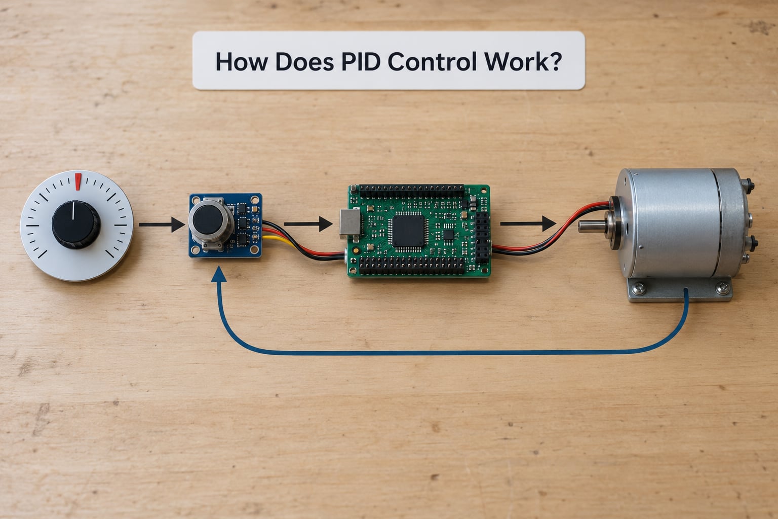
A control loop repeats the same six steps over and over, usually every few milliseconds. Something sets the target. A sensor measures the actual value. The controller subtracts one from the other to get the error. It calculates an output from that error. An actuator moves. Then the sensor sees the result and the cycle starts again. That last part — the measurement feeding back into the next calculation — is what makes it closed-loop control.
Without the feedback, you have open-loop control: send a fixed output and hope. A heater wired to a fixed 60 percent duty cycle, a stepper commanded for a fixed number of pulses, a motor given constant power on a guess. Those work fine until conditions change. Add load, change the water temperature, turn up the wind, and the actual value drifts away from the target with nothing to notice.
Here is one loop updating a heading hold. Target heading stays at 90 degrees while a current pushes the boat off line.
| Loop step | Setpoint | Sensor reading | Error | Controller output |
|---|---|---|---|---|
| 1 | 90 deg | 84 deg | +6 deg | Rudder 30 percent to starboard |
| 2 | 90 deg | 87 deg | +3 deg | Rudder 22 percent to starboard |
| 3 | 90 deg | 95 deg | -5 deg | Rudder 8 percent to port |
| 4 | 90 deg | 90 deg | 0 deg | Rudder returns to centre |
Note what the derivative term is doing in steps 3 and 4. Between loop 2 and loop 3 the error swung from +3 to -5, so the boat is closing on the target fast. A controller that keeps pushing proportionally overshoots. The derivative term reads that swing and damps the command before the rudder gets there.
What Do the P, I, and D Parts Do?
Proportional reacts to the error right now
P is the term you will feel first. Its output is the current error multiplied by a gain, Kp. Error of 6 degrees with Kp of 5 gives a rudder command of 30 percent. Raise Kp and the boat turns harder and reaches the target faster; lower it and the response gets softer and slower.
The catch is that P alone can never hold the target exactly. Suppose your boat needs 15 percent rudder just to cancel a steady cross-current. With Kp at 5, that means an error of 3 degrees — and the boat will sit there, permanently 3 degrees off, all day long. That permanent gap is called steady-state error, and it is the reason P-only control is rarely enough on its own.
Integral remembers the errors that came before
I adds the error up over time, so a small residual offset does not stay small. If the boat sits 3 degrees off, those 3 degrees keep accumulating every loop, and the integral output grows until it forces the boat onto the line. Once the error reaches zero and stays there, the accumulator stops growing and holds whatever value cancelled the disturbance.
That memory is also I’s main risk: integral windup. If the rudder servo is already at its limit and cannot deliver the requested correction, the accumulator keeps growing anyway. When the boat finally comes around, the stored value dumps into the rudder and throws it far past the target. Most library implementations include anti-windup for exactly this, and it matters on small boats where currents are strong and actuators are small.
Derivative predicts where the error is heading
D looks at the slope of the error between loops — how much the error changed while the loop ran. Error dropping from +6 to +3 tells you you are closing in, so the D term contributes a braking push in the opposite direction. It adds damping, which is why full PID settles more gently than PI.
D is the term beginners leave off first and regret it most on anything that overshoots badly. It is also the term that amplifies sensor noise, because noise is fast change, and D cannot tell fast change from real motion. A cheap magnetometer on a boat, a noisy potentiometer, a vibrating IMU — the derivative term turns that jitter into a buzzing actuator. Two standard fixes: take the derivative of the measurement instead of the setpoint, which avoids derivative kick when you change the target, and low-pass filter the derivative input.
How the three terms compare
| Term | Looks at | What it fixes | Typical tuning problem |
|---|---|---|---|
| P | Present error | Speed of response and basic correction | Too high and it oscillates; too low and it is sluggish |
| I | Accumulated past error | Permanent offset and steady disturbances like current | Too high and it overshoots, then hunts |
| D | Rate of change of error | Overshoot and settling time | Too high and sensor noise drives the actuator |
The practical question is not “P, I or D” but which combination you need.
| Controller | Steady-state error | Overshoot | Setup effort | Typical use |
|---|---|---|---|---|
| P only | Never fully removed | Often high | One gain | Fast, simple loops where a small offset is acceptable |
| PI | Driven to zero | Moderate | Two gains | Motor speed, thruster thrust, temperature, slow processes |
| Full PID | Driven to zero | Damped | Three gains | Heading hold, position control, anything overshooting badly |
How Is PID Control Used in Marine Robots?
Boats are a good classroom for PID because they fight you. Currents, gusts, and a hull that responds differently at different speeds mean the perfect gain for a flat pond is wrong the moment the wind picks up. Feedback loops are how a small robot keeps its heading anyway.
Heading hold. A magnetometer or GNSS reports the course over ground, the controller compares it to the waypoint bearing, and a rudder or differential thrusters apply the correction. This is the classic marine PID loop, and it is usually run at 5 to 20 Hz so the loop sees the boat’s response to the current rudder command rather than just reacting to fresh noise.
Thruster and motor speed loops. A brushless thruster commanded to 40 percent should actually produce 40 percent of its no-load speed. Load changes with water, so a tachometer or an ESC feedback line feeds the loop, and I removes the droop you would otherwise see at low throttle.
Sail or keel trim. On a sailing robot, sail angle tracks an apparent-wind target. The actuator moves slowly, so the process is slow, and PI is almost always enough. Adding D here mostly amplifies wind-vane jitter.
Depth hold. A pressure sensor or echo sounder reports depth, and the controller changes ballast or thruster output to match the commanded depth. Disturbances come from waves, so this loop lives or dies on how well I handles a persistent push.
Station keeping. Hold a position over a mark using GNSS coordinates. Wind and current are constant disturbances, which is precisely the situation integral action exists for.
One recurring confusion on the NI community forums is what the controller output physically means. It depends on your actuator: a percentage of full scale, an absolute position in degrees, or a PWM duty cycle. Choose the unit your actuator understands, convert at the edge of the loop, and keep the controller’s numbers in one consistent unit so tuning stays sane.
What Are the Main Benefits and Limitations?
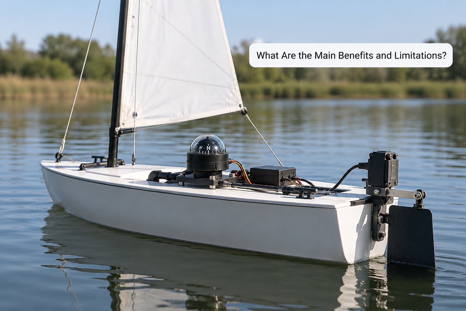
PID is still the most widely deployed control algorithm in the world, and in 2026 it runs on everything from pocket thermostats to industrial reactors. It wins for three reasons: the structure is trivial to compute, it needs no model of the system it controls, and three gains are enough to get most physical processes into decent shape. A microcontroller with a few timers handles it, and the same controller works across wildly different hardware.
The limits are just as clear. PID handles one input and one output cleanly, so a boat that must balance heading against sail trim may need two separate loops. It is a linear controller, which means a rudder that behaves differently at low speed and high speed will need different gains or a feed-forward term. And it has no idea what is about to happen: it reacts, so it will always be a half step behind a sudden gust.
Sensor quality sets the floor. Noisy measurements, dropouts, and long dead times between command and response all show up directly in the output. A heading hold built on a cheap magnetometer mounted next to an ESC will fight its own noise no matter how well it is tuned.
And for slow thermal processes — a heater in a box, a fridge — plain on/off control is often the better answer. A thermostat that switches the element fully on below setpoint and fully off above it needs no tuning at all. PID earns its keep when the process has inertia and gets disturbed.
How Do You Tune a PID Controller?
Tuning is where most beginners stall, because textbooks present it as an optimisation problem. It isn’t. It is a sequence of experiments, and the order matters more than the method.
1. Fix the loop time and the units first. Run the loop at a fixed rate, usually 10 to 50 times faster than the process responds. Pick one unit for the error and one for the output and write them down. A loop whose rate drifts is impossible to tune.
2. Do an open-loop step test. Disable the loop, give the actuator a fixed output, and watch how the measurement moves. You are after two numbers: how far it moves (process gain) and how long it takes to settle. Do this on calm water with a low output.
3. Start with P only. Set Ki and Kd to zero. Raise Kp in small steps until the response gets a little lively. When you see clear repeating oscillation, back off by half. That is your proportional gain.
4. Add a small amount of I. Watch the residual offset after a disturbance — a steady cross-current on a heading hold is the easiest test. Raise Ki until offset disappears within a few seconds, then back off. If overshoot and hunting appear, halve Ki.
5. Add D last, and only if needed. If the response overshoots and rings, add a little Kd to damp it. Change one gain at a time and write down what happened, or you will not know which change fixed what.
6. Add anti-windup and repeat in real conditions. Clamp the output to the actuator’s real limits. Then repeat under the disturbances that matter — wind, current, a heavier load — because gains tuned in flat water rarely survive a rough field test.
Ziegler-Nichols is the famous rule of thumb for this: deliberately set the loop oscillating hard enough to find a critical gain and its oscillation period, then calculate all three gains from two numbers. It gets you a workable controller fast. It also tends to hand you an aggressive loop that shakes hardware and sensors, so most practitioners back the gains off afterward.
Frequently Asked Questions
What does PID stand for?
PID stands for Proportional, Integral, Derivative. Those three names describe three ways of looking at the same error value: how far off you are right now, how far off you have been in total, and how quickly that gap is closing. A controller sums three scaled versions of the error and uses the total to decide how hard to push.
What is the main purpose of a PID controller?
The main purpose of a PID controller is to hold a measured value at a target even when conditions change around it. It closes the loop: it reads a sensor, compares that reading to the setpoint, and adjusts an actuator until the difference shrinks toward zero. That feedback is what lets a boat hold a heading against wind or a heater hold temperature as the room cools.
Are PID controllers still used?
Yes, PID remains the most widely deployed control algorithm in industry. It runs on microcontrollers, PLCs, flight controllers, motor drives and hardware in every consumer thermostat. Newer methods such as MPC and adaptive control get attention in research, but PID is cheap, easy to tune and works on most physical processes.
What should I set Kp, Ki and Kd to as a beginner?
There is no universal starting value, because the numbers depend on your process gain, actuator limits and loop rate. Start with Ki and Kd at zero and set Kp low, then raise Kp until you see mild oscillation and back off by half. Add a small Ki to remove offset, and add Kd only if the response overshoots badly.
Why does my PID controller oscillate?
Oscillation almost always means too much gain, and the loop is correcting faster than the process can respond. Lower Kp first. If the hunting started when you added integral action, reduce Ki or add anti-windup clamping. If it appeared when you added Kd, your sensor noise is being amplified and the derivative term needs filtering or should be dropped.
What is the Ziegler-Nichols rule for PID tuning?
Ziegler-Nichols is a two-step procedure. First, raise proportional gain with the other terms off until the loop sustains a steady oscillation, and note that critical gain and its period. Second, use those two numbers to calculate all three gains from published tables. It produces an aggressive response quickly, so most people scale the result back before using it.
Conclusion
PID control compares what you want against what a sensor reports, then corrects using the present error, the accumulated past error and the rate of change. Start small: pick one variable to hold, measure it reliably, and get a proportional loop running before adding anything else. Once a plain P loop works, adding integral and derivative is an adjustment rather than a rewrite.