Here is the short answer: an IMU, or inertial measurement unit, contains three-axis accelerometers and three-axis gyroscopes that measure how hard it is accelerating and how fast it is rotating, and a fusion algorithm on board turns those raw readings into an orientation estimate. Adding a three-axis magnetometer gives it an absolute heading reference. Understanding how IMU sensors work means understanding the physics underneath that chip and the drift that follows it into every deployment at sea.
No, an IMU is not just an accelerometer, which is the single most common confusion on this topic. An accelerometer alone can only see gravity plus motion, and it cannot tell rotation from tilt. The gyro is what makes yaw observable.
This guide walks from the proof mass inside the sensor package out to a heading number your autopilot can steer with, then covers the marine specifics: thruster vibration, a steel hull sitting next to your magnetometer, saltwater, and how to calibrate the thing so the bias estimate survives a power cycle. It is written for people building field instruments, AUVs, autonomous surface craft and sailboats that must keep working when GNSS does not.
Table of Contents
- What Is an IMU Sensor?
- How IMU Sensors Work
- What Does an IMU Measure?
- How Does an IMU Estimate Orientation?
- What Is Sensor Fusion in an IMU?
- Why Are IMUs Important for Sailing Robots?
- What Affects IMU Accuracy?
- How Do You Calibrate an IMU?
- How Do You Choose an IMU for a Marine Robot?
- How Do You Mount and Use an IMU Safely?
- Frequently Asked Questions
- Conclusion
What Is an IMU Sensor?
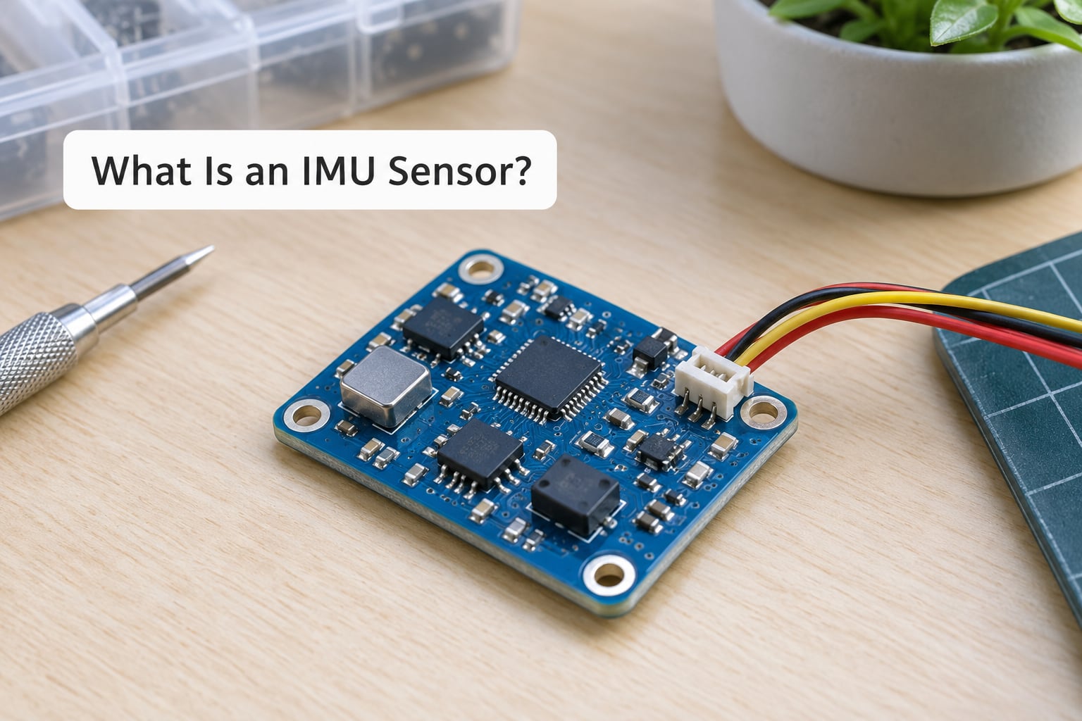
An inertial measurement unit is a small electronic module that reports a body’s motion relative to an internal reference frame. In practice it is three orthogonal sensor channels, one pair per axis, plus the electronics to digitise them and often a processor running the fusion algorithm.
Most modules sold today are 6-axis, meaning three accelerometers and three gyroscopes. Add a three-axis magnetometer and you get a 9-axis IMU, which can compute absolute heading as well as attitude.
It is worth being precise about what belongs to the IMU and what sits next to it. A magnetometer on its own is a compass, not an IMU. A barometer measures pressure, which becomes depth or altitude, and tells you nothing about rotation. GNSS gives you position and heading but only above water with a clear sky. And LiDAR measures distance to a surface by timing light. An IMU is the one that keeps working when all of those stop.
That last point is the reason marine robotics cares about this question. Underwater, in a concrete tunnel, inside a shipping lane with a bad sky, or during a GNSS outage, the IMU is often the only motion reference left on the vehicle.
How IMU Sensors Work
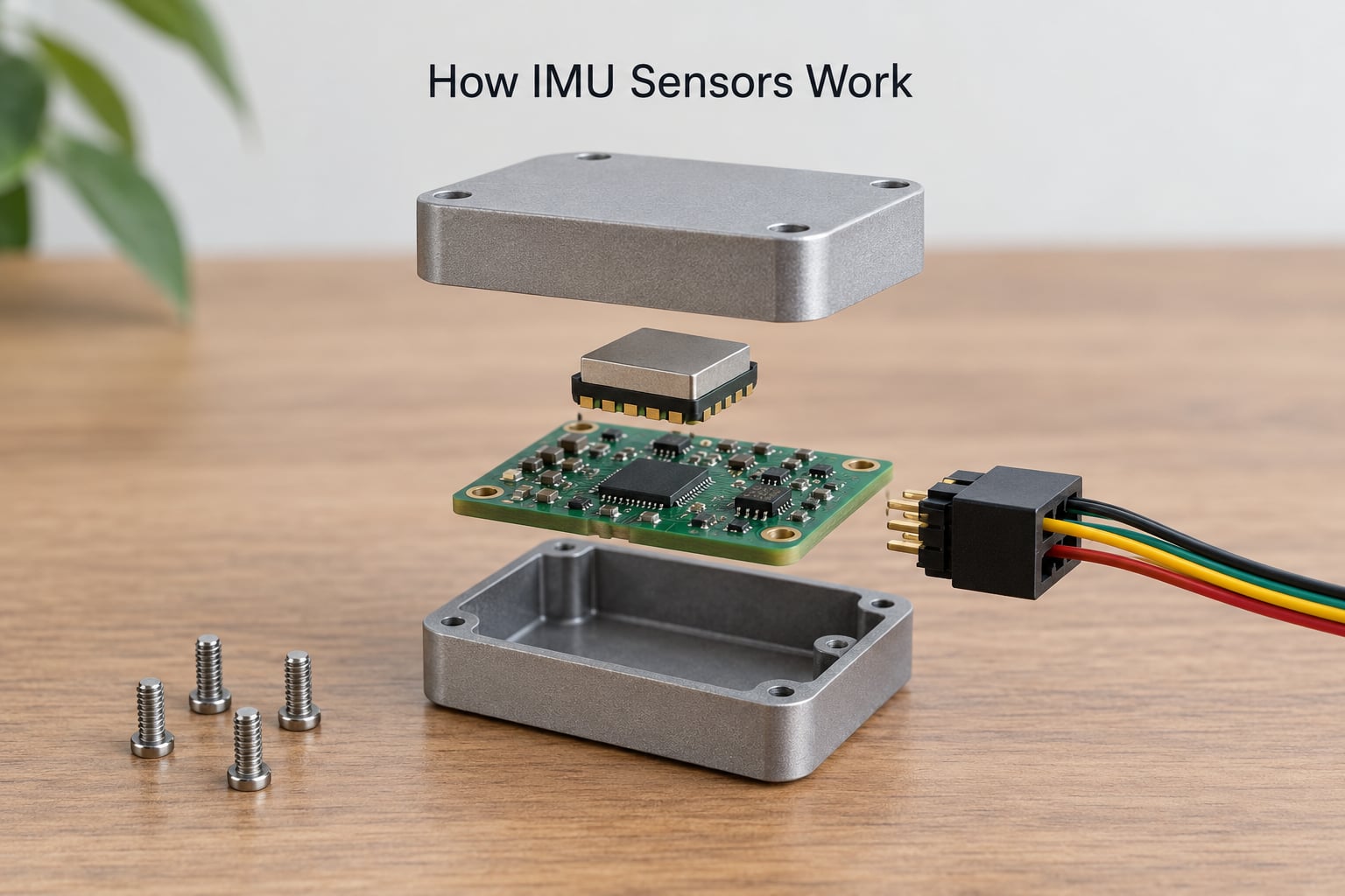
Every inertial sensor in an IMU works the same way at the core: move something inside the sensor, and measure that movement. The proof mass is the something. Whether it moves by a spring, by a vibrating tine, or by an optical path difference, the principle is the same as a seismograph that you wear like a wristwatch.
How an accelerometer works: proof mass, spring, capacitor
A tiny silicon proof mass is suspended inside the accelerometer frame on etched springs. When the sensor case accelerates, inertia makes the proof mass lag behind the case, so the mass displaces relative to the frame. That displacement is proportional to the force on the mass, which by Newton’s second law is mass times acceleration.
The springs make the mechanical part linear and stable: the restoring force follows Hooke’s law, so a steady acceleration settles at a steady offset. The displacement itself is measured capacitively, using a differential capacitor made of fixed and moving electrodes. Moving changes the gap on one side and the opposite gap on the other, and the electronics look at the difference between the two capacitance values. That difference cancels out parasitic capacitance and gives a clean signal.
Open-loop accelerometers read the displacement directly, which means real acceleration can drive the proof mass into the end stops. Closed-loop designs apply a feedback force to keep the mass centred and measure the feedback instead, which extends the range and improves linearity at the cost of more circuit.
How a gyroscope works: the Coriolis effect
A MEMS gyroscope is a small vibrating structure driven at resonance on a drive axis. When the whole sensor rotates about an axis perpendicular to that drive axis, the rotation appears as a sideways deflection of the vibrating mass. That deflection is the Coriolis effect, the same term you meet in rotating platforms and in Foucault pendulums.
The Coriolis deflection is tiny, so the sensor measures it capacitively too, using a second pair of electrodes on the sense axis. The ratio of that Coriolis deflection to the drive amplitude and drive frequency gives the rotation rate in degrees per second. Three of these arranged orthogonally give you three-axis angular rate.
Higher-grade gyroscopes work on the same idea with light instead of silicon mass. A fibre optic gyroscope sends light around a fibre loop in both directions and compares the two arrival times; the difference is the Sagnac effect, and it is directly proportional to rotation rate. A ring laser gyroscope does the same thing with two counter-rotating laser beams. Both are far more accurate than MEMS and much larger, power-hungry and expensive.
How a magnetometer works: Hall effect and magnetoresistance
The third sensor measures the Earth’s magnetic field. Two technologies dominate. Hall-effect sensors use a current-carrying semiconductor that develops a voltage perpendicular to both the current and the field. Magnetoresistive sensors instead use resistors whose resistance changes slightly in the presence of a field. Either way the output is a field vector in microtesla.
This is the only absolute heading reference on board, which is exactly why it is also the sensor most easily ruined. On a steel boat, current-carrying cable, a motor or a speaker magnet, the local field can be several times stronger than Earth’s, and the heading goes with it.
How IMU sensors work end to end: the five-step signal chain
- Mechanical motion. The proof mass or vibrating tine moves relative to the sensor case.
- Electrical signal. Capacitance changes, or in optical units a time or frequency difference, appear as a small analog signal.
- Conditioning. An analog front end amplifies and filters the signal, then an analog-to-digital converter samples it.
- Decoding. The digital value is converted using the calibrated scale factor into real units, micro-g for the accelerometer, degrees per second for the gyro, microtesla for the magnetometer.
- Fusion. A filter combines the channels into attitude, heading, and often velocity and position estimates.
That last step is where most of the engineering lives, and where most of the disappointment too. Steps one through four are physics. Step five is software, and it is the step that decides whether your robot knows which way it is pointing.
What Does an IMU Measure?
Three quantities come out of a 9-axis IMU, and a fourth sensor on a marine vehicle usually adds depth. It helps to keep them straight, because mixing them up causes real bugs.
| Sensor | Measures | Weak spot |
|---|---|---|
| Accelerometer | Specific force along three axes, reported in g | Gravity and motion are mixed together in one number |
| Gyroscope | Angular rate about three axes, in degrees or radians per second | Bias offset that slowly integrates into angle error |
| Magnetometer | Magnetic field vector in microtesla | Distorted by steel, motors and current-carrying wiring |
| Barometer | Static pressure, converted to depth or altitude | Affected by waves and by temperature |
| GNSS | Position, velocity and a coarse heading | Unavailable underwater, indoors or under a bad sky |
Specific force is the term that trips people up. An accelerometer at rest on a table reads about 1 g on its vertical axis, because the sensor is measuring the reaction to gravity rather than gravity itself. That is the signal that gives you a gravity reference. If the sensor is in free fall, it reads nearly zero because everything is accelerating together.
What an IMU cannot tell you is worth stating plainly. It cannot give absolute heading from six axes alone. It cannot give you a position fix, because position comes from double-integrating acceleration, and the smallest bias becomes an unbounded error. And it cannot detect a slow steady turn that the accelerometer’s gravity vector is ambiguous about.
That is the honest summary of the forum consensus too. The integration, not the sensor, is usually the limiting factor, which is why people who fight drift in software end up adding GNSS or another external reference.
How Does an IMU Estimate Orientation?
Roll and pitch are the easy pair, because gravity points down and a level vector gives an absolute reference no matter how long you have been running. Point the accelerometer’s known axes at the gravity vector and you have two angles, usually through an atan2 of the horizontal and vertical components.
Yaw is the hard one. Rotation about the gravity axis does not change where gravity points, so the accelerometer is completely blind to it. Yaw can only come from integrating the gyroscope, and integrating means every bias becomes angle error that grows with time.
Two more refinements matter in practice. First, most implementations do not store pitch, roll and yaw directly, because Euler angles break down when pitch approaches 90 degrees. A quaternion, four numbers that always stay normalised, avoids the singularity.
Second, tilt sensors used on boats rely on gravity, which swings with wave motion and roll, so a compass with a heavy tilt compensation and low-pass filter is much more usable than a bare magnetometer read straight from the bus.
Why yaw always drifts and what gyrocompassing does about it
Yaw drift is structural, not a defect. The gyro’s bias uncertainty of even 0.01 degrees per hour is invisible in the rate output and completely visible after an hour of integration. On a long ocean transect that error is measured in degrees, and degrees of heading error turn into metres of cross-track error very quickly.
Gyrocompassing is the partial fix. When the vehicle is genuinely accelerating in a known direction, gravity and linear acceleration resolve differently in the body frame, so the difference gives an independent yaw estimate. It only works while acceleration is significant, and it is useless on a sailboat running quietly at steady speed.
What Is Sensor Fusion in an IMU?
Sensor fusion is the process of combining the noisy channels into one estimate that is better than any of them alone. The gyro is smooth and responsive but drifts. The accelerometer is absolute for tilt but noisy. The magnetometer is absolute for heading but jumpy. Fusion blends them so each weakness cancels.
The simplest useful version is the complementary filter. Trust the gyro for the short term and the accelerometer for the long term, with a time constant that decides how quickly corrections are allowed. Many small modules ship with exactly this running in firmware.
A Kalman filter is the more general answer. It predicts where the attitude should be based on the gyro, measures that prediction against every available sensor, and weights the correction by how much it trusts each source based on its own estimated uncertainty. As an accelerometer drops out under vibration, its weight falls on its own. The extended Kalman filter does the same thing while allowing a state error between the filter and the navigation estimate, which is what makes it the usual choice for a full inertial navigation system.
Where the correction comes from is a design decision with real consequences at sea. A surface vessel can use GNSS heading and position. An underwater vehicle can use a Doppler velocity log or an acoustic baseline fix. Some systems fuse in a barometer for vertical reference and a pressure sensor for depth.
Why Are IMUs Important for Sailing Robots?
On a boat, the IMU is what turns a compass reading into a control input. Here is where the abstract physics meets a hull.
Sail trim against the apparent wind. Apparent wind is the vector sum of true wind and your own motion, so it changes as the boat accelerates. Getting the sail on the right side of that vector needs a heading estimate that holds up when the boat rolls, pitches and accelerates through a wave.
Heel and capsize detection. A sustained roll angle far past the design range is a real event, not a nuisance. A gyroscope plus accelerometer pair separates a steady heel from a wave-driven roll oscillation, which matters when deciding to reef or power down.
Wave motion compensation. A hull-mounted magnetometer swings wildly as the boat pitches. Fusing it with the gyro and letting gravity keep the tilt reference gives a heading that stays usable in a seaway.
Station keeping and line tension. Holding station or keeping a tow cable clear of the hull depends on knowing the vessel’s motion relative to the water and the seabed, not just to the world. A vessel that only trusts GNSS loses all of it the moment the antenna is submerged.
Recovery from a capsize or knockdown. The robot has to know it is upside down. A gravity-referenced attitude estimate answers that question immediately, even underwater and in the dark.
IMU versus LiDAR versus GNSS: what each one actually tells you
| System | Reports | Update rate | Fails when |
|---|---|---|---|
| IMU | Acceleration, angular rate, attitude | 100 Hz to kHz | Long run without aiding (drift) |
| GNSS | Position, ground speed, coarse heading | 1 to 20 Hz | Underwater, indoors, poor sky, jamming |
| LiDAR / laser scan | Distance to surfaces, local geometry | 1 to 50 Hz | Clear water, sparse features, range limit |
| Pressure sensor | Depth | 10 to 100 Hz | Waves and swell load it with dynamic pressure |
They are complements, not competitors. The IMU is the only one that measures the vehicle itself, at high rate, with no external signal, which is why every serious marine robot carries one even when it also carries everything else.
What Affects IMU Accuracy?
Sensors arrive from the factory within their specification. Then you mount them on a boat and everything changes. Here is the list that actually costs you accuracy, roughly in order of how much it hurts.
Vibration and vibration rectification error
An engine, a thruster or a bad panel generates vibration well above the sensor’s flat noise band, and linear accelerations get averaged out as random noise. The nastier effect is that vibration biases the output, and it does so proportionally to the vibration amplitude, frequency and shape of the mounting. It looks like a slow turn that never appears in the data.
Temperature
Bias is a function of temperature, and a hot sensor in a pressure housing can run 20 degrees above ambient. A single calibration at one temperature does not cover that span, which is why calibrated modules publish a bias versus temperature curve rather than one number.
Bias instability and initial bias
Bias instability, quoted in degrees per hour, is how much the gyro bias wanders over an hour with the unit perfectly still. Initial bias is the offset it powers on with, and it can be far worse than the instability figure. Power-on-to-power-on repeatability tells you whether the calibration you did last week is still valid, and it is the number most often ignored on cheap modules.
Noise density and random walk
Noise density, quoted in micro-g per square root hertz or degrees per hour per square root hertz, is the short-term jitter. Angle random walk is the separate error that comes from integrating white noise, and it grows with the square root of time. Bias-driven drift, which is the one that matters for a mission, grows with time itself.
Magnetic interference
On a steel or aluminium boat with an engine, the compass heading can be off by 30 degrees or more, and worse, off by a different amount depending on where you drifted. This is the first thing to suspect when heading errors track engine load or battery state.
Mounting alignment, resonance and scale factor
If the sensor’s axes do not line up with the vessel’s axes, your roll and pitch output mixes into heading, and most of that shows up as yaw error. A sensor mounted on a thin plate also has a mechanical resonance somewhere in the working band; if thruster excitation lands near it, the response is far larger than the acceleration applied.
Bandwidth and sample rate
These are not the same number. Sample rate is how often you get a reading. Bandwidth is the frequency range where the reading is accurate. You cannot filter your way out of motion faster than the sensor can actually measure it, and a filter applied too aggressively adds lag, which is a control problem rather than a sensor problem.
A worked drift example
Take an illustrative gyro with a bias instability of 1 degree per hour, powered on without calibration. Integrating that gives roughly 1 degree of heading error after an hour, and it does not come back. An hour of continuous GNSS-aided heading would have removed it entirely.
Now take accelerometer velocity random walk of 0.1 m per second per square root hour and integrate position. After one hour, a single-axis position uncertainty is on the order of 0.1 times 60 to the 2/3, which is roughly 24 metres. After two hours it is about 1.4 times larger, not twice as large, because white-noise error grows as the square root of time. This is why everyone on the forums says dead reckoning from an IMU alone is a short-duration tool, and why the fix is always an external reference rather than a better chip.
How Do You Calibrate an IMU?
Calibration is how you turn the numbers a sensor reports into numbers you can trust. Do it properly before the sensor ever sees salt water.
Step one is warm up. Leave the unit powered on a stable surface for 10 to 20 minutes. Bias specs assume a settled temperature, and calibrating a cold sensor gives you a bias offset that will be wrong within minutes.
Step two is gyro bias estimation. Keep the sensor dead still and average the gyro output on each axis. That average is the bias, and subtracting it is usually the single biggest improvement you will make. Run it for at least a minute and make sure nothing is touching the table.
Step three is the six-position static accelerometer calibration. Place the unit level, then nose up, nose down, left side up, right side up, and upside down, letting it settle at each orientation. From those six readings you get the scale factor and the axis misalignment for each accelerometer, which corrects the classic tilt error when pitch is not what the raw vector says.
Step four is magnetometer calibration, and only if you have a magnetometer. Rotate the unit slowly through as many orientations as you can, ideally all three axes. The resulting ellipsoid gives you the hard iron offset from ferromagnetic material and the soft iron scale matrix from the vessel’s steel. Do this with the sensor in its final housing and mounted position, because the boat changes the answer.
Step five is verification. Power-cycle the unit, repeat steps two through four, and compare. If the gyro bias estimate moves more than a small fraction between power cycles, you are looking at poor repeatability, not a calibration mistake.
How Do You Choose an IMU for a Marine Robot?
Start from the mission, not the sensor. Write down how long the vehicle must hold a heading without an external fix, how violent the motion is, and what happens when the estimate is wrong. Those three answers cut the field fast.
| Technology | Typical bias instability | Character | Typical fit |
|---|---|---|---|
| Consumer MEMS | 10 to 100 deg/hr | Tiny, cheap, mount-sensitive | Hobby craft, prototyping |
| Industrial MEMS | 1 to 10 deg/hr | Wide range options, good temperature behaviour | Small surface craft and AUVs |
| Quartz MEMS | 0.5 to 2 deg/hr | Excellent bias stability, pricey | Long-duration survey work |
| Fibre optic gyroscope | Below 0.05 deg/hr | No moving mass, large and power-hungry | Marine survey and navigation |
| Ring laser gyro | Below 0.01 deg/hr | Reference-grade, needs care and space | Shipboard reference systems |
Read the datasheet for these figures, and know what each one means. Bias instability tells you the standing still error floor. Noise density tells you how much the output jitters at a given bandwidth. Angular random walk tells you the heading error after a known interval. Scale factor in ppm tells you how far your rate or acceleration readings are off after calibration. Range tells you whether you will clip when the boat takes a wave, and bandwidth tells you whether it can even see the motion.
Also check the interface. I2C is simple but clocked and noisy-prone, which is a poor match for a long cable run next to a thruster. SPI is faster and more deterministic, and UART is a reasonable choice at lower rates. Match the supply voltage to your rail, and check current draw against what your power budget can carry through a full mission, including cold conditions when battery capacity drops.
Redundancy is worth considering for anything that spends days out of sight. A second IMU at a different mounting location gives you the only genuine cross-check you have at sea, and the disagreement between the two is a genuine health signal.
How Do You Mount and Use an IMU Safely?
Mounting is where a good sensor becomes a bad measurement. A few practices carry most of the weight.
Rigid and aligned. Mount the sensor on solid structure that runs to the hull, never on a thin plate or a cable gland housing, and align its axes with the vessel’s fore-and-aft and athwartships lines. Document the offset angles you used.
Away from interference sources. Place the unit as far as practical from thruster motors, magnetometers, heavy steel, high-current cabling, and the engine block. If a compass and an IMU must live together, put the magnetometer on the far side of the vessel and keep it on its own short cable.
Strain relief and strain isolation. The cable is often the real vibration path. Use a proper strain relief at the housing and keep the sensor-side cable short. Do not mount on rubber isolators if you want a rigid body measurement, but do avoid rigidly bridging two structures that vibrate differently.
Protection for salt water. Put the electronics inside a pressure-rated housing with a proper seal, use conformal coating on the board, and add strain relief so the cable cannot carry water inward. Rinse with fresh water after every deployment and dry the connector face before it is stored.
Log raw data, not just fused output. Store the raw accelerometer, gyro and magnetometer samples alongside the fused attitude. When the heading looks wrong at 2 a.m., the raw log tells you whether the sensor lied or the filter did.
Validate against ground truth. Do a controlled run on land and on a calm day, comparing the IMU heading with a separate compass or GNSS heading, and compare the attitude against a spirit level or inclinometer. Do this before the robot goes out alone.
Re-calibrate after any refit. Moving the sensor, changing the housing, adding a new motor or a new battery bank all invalidate the calibration and often the magnetometer model. Treat every refit as a new install and repeat the procedure.
Frequently Asked Questions
Do IMUs drift without GPS?
Yes, always. A gyroscope measures rotation rate, so estimating heading means integrating that rate over time, and the smallest bias offset becomes a growing angle error. Roll and pitch stay bounded because the accelerometer’s gravity reference pulls them back. Yaw has no such reference, which is why an unaided six-axis IMU is a short-duration instrument. Adding GNSS, a Doppler log or an acoustic fix is the standard fix.
Can an IMU be used underwater?
Yes. An IMU needs no external signal, so it works perfectly well submerged, which is exactly why AUVs rely on it. What does not survive underwater is the magnetometer, because the housing and the surrounding steel distort the field badly. Most underwater vehicles use a six-axis IMU plus a separate depth sensor and rely on Doppler velocity or acoustic ranging for heading and position instead of a compass.
What sample rate does a marine robot need?
For control of a small surface craft, 100 to 200 Hz is usually enough to characterise wave motion and hold attitude loops. Underwater vehicles that manoeuvre quickly or watch seafloor features often run higher, and some survey systems log at hundreds of Hz for post-processing. Pick a sensor whose bandwidth genuinely covers the motion you care about, because filtering cannot recover detail the sensor never resolved.
How accurate is an IMU over a long mission?
It depends on two separate numbers, not on the marketing figure. Bias instability in degrees per hour tells you the heading error floor for a stationary unit, and random walk tells you how error grows with time. As a rough guide, a good industrial MEMS module holds attitude well for minutes but needs external aiding for hours, while a fibre optic gyroscope can carry a heading through a full working day unaided.
Is vibration ruining my IMU readings?
Probably, if you are on a small powered craft. Vibration shows up as a slowly wandering offset that looks like a constant turn, and it grows with vibration amplitude and with how close the mounting resonance sits to the excitation frequency. Symptoms are a heading error that tracks engine load, or attitude noise that increases with RPM. Check by recording raw data with the engine off, idle, and at working load, then compare the gyro average on each.
Is a 6-axis IMU enough for marine robotics?
For attitude, yes. Six axes give you pitch and roll reliably and yaw as a drifting but useful estimate, which is enough for control loops that use GNSS or a Doppler log for correction. Add a magnetometer only if you are on the surface, far from steel and high-current wiring. Below the waterline, most builders drop the magnetometer entirely and spend the money on a better gyro instead.
Conclusion
The whole of how IMU sensors work comes down to one idea repeated three times: a physical thing inside the sensor moves, that movement becomes an electrical signal, and software turns those signals into an estimate of motion. Accelerometers get you tilt, gyroscopes get you rotation, and a magnetometer gives you an absolute heading that is trustworthy only in a clean magnetic environment.
Four things to do first, in order. Pick the sensor from your mission duration rather than from a feature list, then calibrate it properly on a stable surface with a warm unit and a six-position sequence. Log raw sensor data next to the fused attitude so you can tell a bad sensor from a bad filter. Then validate the estimate against ground truth under the real vibration and motion of your vessel, because a sensor that reads perfectly on a workshop table tells you very little about a boat in a seaway.