Antenna height affects radio range because it decides how far past the Earth’s curve a signal can travel before the surface blocks it. VHF and UHF travel in straight lines, so the working range between two stations is the sum of their two horizon distances, and each of those grows with the square root of the antenna height. A 6 ft antenna sees roughly 3 miles. The same antenna at 100 ft sees about 12.
Key takeaways
- Line-of-sight range equals the horizon distance from each antenna, added together.
- Horizon distance scales with the square root of height, so modest height changes move range a long way.
- Four times the height at both ends doubles the horizon range, worth about 6 dB of link budget. That is the same as quadrupling transmit power.
- Real-world range usually lands at 60-80 percent of the horizon prediction, so treat the table as a ceiling.
- On HF bands, extra height lowers the take-off angle and can cost you signal instead of adding it.
Table of Contents
- How Antenna Height Affects Radio Range at Sea
- How the Radio Horizon Is Different From the Visible Horizon
- How Antenna Height Affects Line-of-Sight Links
- What Else Determines the Useful Radio Range?
- How to Choose and Test an Antenna Height for a Marine Link
- What Are the Safety and Practical Limits?
- Frequently Asked Questions
- Does a taller antenna always increase radio range?
- How much antenna height is needed for a marine radio link?
- Do both ends of a radio link need taller antennas?
- How does antenna height affect the Fresnel zone?
- Can I calculate radio range from the distance between two vessels?
- What is a reasonable antenna height for an ocean-robot link?
- What to Do First
How Antenna Height Affects Radio Range at Sea
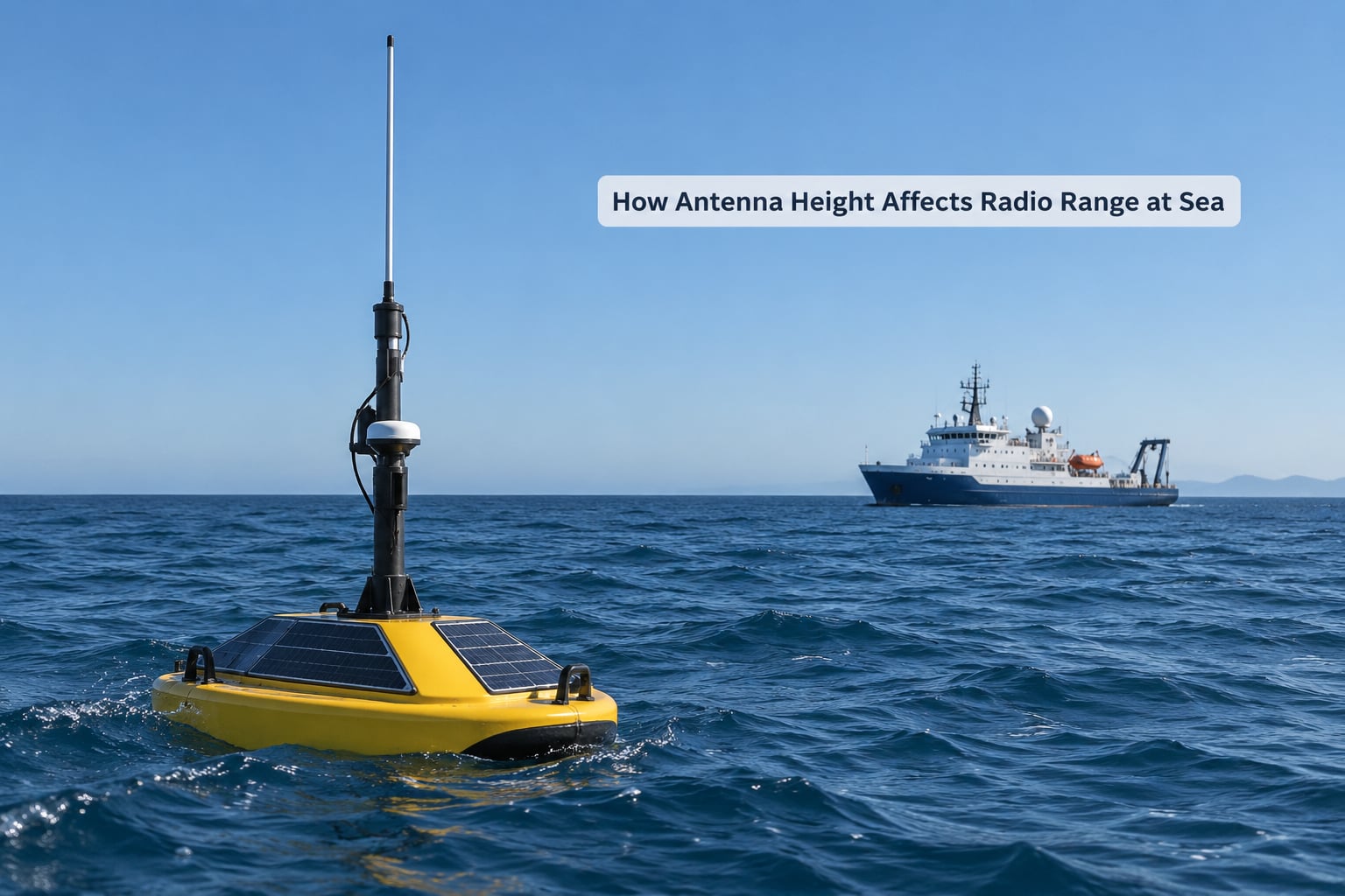
Put the same 25 W VHF radio on a 6 ft handrail and then on a 20 ft mast, and the horizon maths changes by almost a factor of two. Nothing about the radio changed. Only the distance from the antenna to the water did.
That single number sets how far the station can “see” over the curve of the Earth. Every radio horizon figure below assumes a smooth Earth, no terrain, and an unobstructed path between the two antennas. Over open water those assumptions are unusually good, which is why sea-level horizon tables are treated as near-real data by small-craft operators.
| Antenna height | Horizon from one antenna | Range between two antennas at the same height |
|---|---|---|
| 6 ft (1.8 m) | 3.0 miles (4.8 km) | 6.0 miles (9.7 km) |
| 10 ft (3.0 m) | 3.9 miles (6.2 km) | 7.7 miles (12.5 km) |
| 20 ft (6.1 m) | 5.5 miles (8.8 km) | 11.0 miles (17.6 km) |
| 30 ft (9.1 m) | 6.7 miles (10.8 km) | 13.4 miles (21.6 km) |
| 100 ft (30.5 m) | 12.2 miles (19.7 km) | 24.5 miles (39.4 km) |
| 330 ft (100 m) | 22.2 miles (35.8 km) | 44.5 miles (71.6 km) |
| 1,000 ft (305 m) | 38.7 miles (62.3 km) | 77.4 miles (124.6 km) |
| 2,717 ft (828 m) | 63.8 miles (102.7 km) | 127.6 miles (205.4 km) |
Small-craft AIS and VHF users work in exactly these numbers. One forum thread on AIS placement notes that an antenna 1.7 m above sea level sees about 2.5 nautical miles, and two boats at that height make up roughly 5 nm between them. That is the mental model most people already carry without having the formula behind it.
How the Radio Horizon Is Different From the Visible Horizon
The visible horizon is geometric. The radio horizon is that same geometry adjusted for the way radio waves bend through the atmosphere. Because roughly four fifths of the air’s refractive index sits below the marine layer, radio rays curve slightly downward along with the Earth, so a radio signal reaches a little further than the ground you can see.
Engineers account for that with an effective Earth radius of 4/3 the true value. It is a fudge, but a useful one: it lifts every distance in the table above by about 15 percent, taking the coefficient from 3.569 to roughly 4.12 km per square root of height in metres.
What makes this confusing in practice is that height can be measured two different ways. A mast height is height above local ground or deck. A horizon calculation needs height above the average terrain or sea level under the path. Two operators can both say “20 ft antenna” and be 300 ft apart in effective height, which is why range reports copied between boats often make no sense.
How Antenna Height Affects Line-of-Sight Links
Clearance is the part people skip. The direct path between two antennas is only the first requirement, and for anything above about 1 GHz the path has to keep the first Fresnel zone mostly clear as well. That zone is an ellipse-shaped volume around the direct path, and its radius grows with both distance and frequency. For a link in kilometres at gigahertz, the radius in metres works out to about 17.32 times the square root of distance multiplied by frequency. Keeping the middle 60 percent of that radius clear is the usual rule of thumb.
Over open water at VHF this rarely bites. On a UHF telemetry link between a shore station and an ocean robot it bites constantly, because salt water spray, a hull, or a wave crest in the path knocks holes in the zone.
How Much Clearance Does a Marine Link Need?
For a 900 MHz telemetry link of 20 km, the first Fresnel radius is about 73 m, so you want roughly 45 m of clearance through the middle of that ellipse. Over the ocean the only things that intrude are wave crests and the robot’s own mast, so the practical fix is a working height on the vessel rather than a taller shore tower.
Two other losses hide in the same bucket. A long run of thin coax on a small boat eats signal before it ever reaches the antenna, and marine forum threads about VHF height versus gain keep landing on the same point: all the advantages of a higher antenna disappear when the feedline and connectors are poor. Anything after the radio’s output stage matters.
How a Wave Height Changes the Practical Horizon
A calm sea gives you the table. A rough sea shortens the useful path, because a wave crest near the midpoint can block the lower part of the Fresnel zone and because the receiving antenna drops as the vessel pitches. Coastal VHF working distances reported by small boats fall well short of the horizon prediction for exactly this reason, and the gap widens as the sea state builds.
What Else Determines the Useful Radio Range?
Antenna height is usually the biggest lever you control, but it is not the only one, and readers who attribute every range failure to height end up chasing the wrong problem.
| Factor | What changing it really does | Improves signal strength, link margin, or both |
|---|---|---|
| Antenna height | Moves the horizon and clears obstructions | Both, roughly 6 dB per quadrupling at both ends |
| Transmit power | Adds signal at the receiver input | Link margin, 3 dB per doubling |
| Antenna gain | Concentrates energy into a narrower beam | Signal strength, with a narrower receive pattern |
| Receiver sensitivity | Lower noise floor and a quieter listening band | Link margin only |
| Feedline and connectors | Removes loss after the transmitter | Signal strength |
| Polarisation match | Stops mismatch loss between stations | Signal strength |
| Band choice | VHF bends around obstacles, UHF does not | Link margin in cluttered terrain |
| Local noise | Engine ignition, LED drivers, other radios | Link margin through the noise floor |
| Grounding and common mode | Stops the feedline behaving as an antenna | Signal strength, mostly on transmit |
| Sea state and spray | Changes effective height and adds wet-loss | Both, unpredictably |
How to Improve Range Without Raising the Antenna
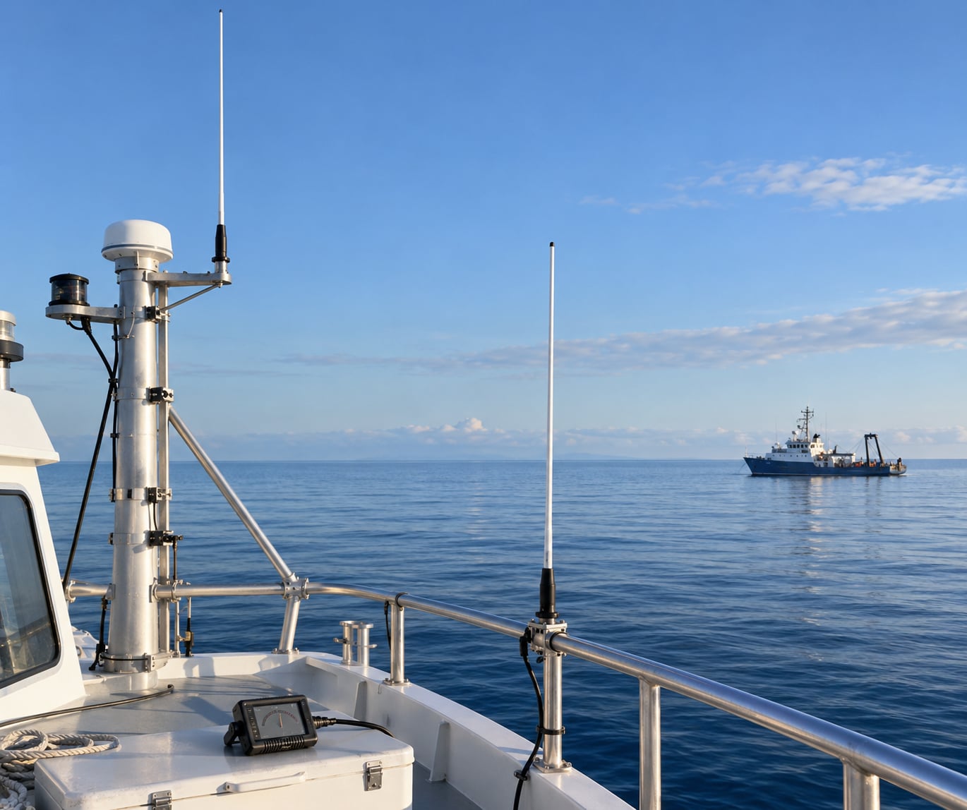
Choose a cleaner mounting point first. A roof-mounted marine antenna beats one down in the cockpit, and a mast above the radar scanner beats one below it, even at the same height above the deck.
Then work through the boring items that usually pay more than another metre of mast: check every connector with a meter, replace a tired coax run, mount a common-mode choke at the radio end, and match polarisation between stations so the receiving pattern is not fighting the transmitting one.
Alignment matters as much as gain on a narrow beam. A 10 dBi antenna pointed three degrees off beam loses more than a cheap antenna aimed correctly, and it loses it in both directions.
On the electronics side, a matched antenna and radio pair beats a mismatched pair with a bigger number on the box. Check the manufacturer’s specification sheet for the connector type, the band, and the mounting clearance, and check the radio’s own manual for the grounding arrangement it expects.
How to Choose and Test an Antenna Height for a Marine Link
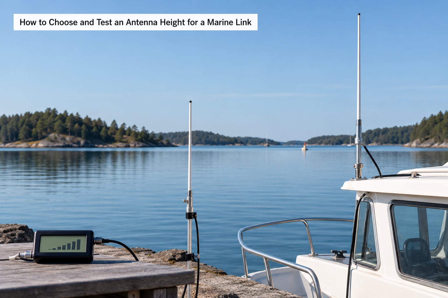
Work through this in order rather than picking a mast length first.
- Define the two endpoints: the vessel, the robot, or the shore station, with the antenna height you have now at each.
- Enter both heights into the horizon formula and record the theoretical ceiling for the link.
- Check the Fresnel requirement for your band and distance, then look for anything that intrudes on it.
- Add a margin for the sea state you actually plan to operate in, not the one on a calm day.
- Pick a mounting height that stays inside the vessel’s structural and legal limits while clearing the rigging.
- Verify RF clearance below and above the antenna, and confirm the mechanical fix holds under load.
That sequence tells you whether height is even the constraint. If the predicted ceiling is already larger than the distance you need to cover, a taller mast buys you nothing, and money is better spent on the feedline or the receiver.
How to Test the Link from a Sailing Robot
Set the radio at a fixed transmit rate and log the results at each of two heights, ten minutes apart on the same course. Record the packet delivery ratio, the received signal strength from the link’s own telemetry, the data rate that holds, and the round-trip latency.
Do one pass at the low height, one at the high height, then repeat. Height effects show up as a consistent difference between the two sets rather than a single good afternoon.
Run the same sequence under way and stopped. A robot pitching in a seaway changes its effective antenna height continuously, and a link that only works flat calm is not a link.
If signal strength improves but delivery ratio does not, the problem sits in the noise floor or the protocol, not in the path. That one test separates most height problems from most equipment problems.
What Are the Safety and Practical Limits?
Masts have a real price. Wind loading on a slender marine whip goes up faster than most people expect, and a rigged boat already carries a full complement of halyards, winches and crew. Guy wires and taller spars also add permits and inspection work, which is one reason so many antennas stay where they are.
Salt water is the other one. Corrosion at the base, at connectors and inside coax runs causes slow losses that look like a height problem because both symptoms show up as “range got worse”.
Keep the antenna clear of people and of anything that moves: rigging, booms, winches, the crane, the A-frame. A whip can be whipped. RF exposure matters once you are above a few watts in a confined space, and lightning protection has to be designed with the mast, not added afterwards.
Electrical work, grounding and lightning protection should go to a qualified marine electrician. Your vessel’s manual and your local radio regulations take precedence over anything here, including antenna height limits set for services such as GMRS and FRS in the US.
Frequently Asked Questions
Does a taller antenna always increase radio range?
Not always. On VHF and UHF, height raises the radio horizon and usually adds real range. On HF bands, a very tall antenna pushes the take-off angle lower, so more of the signal is absorbed by the ground before it reaches the ionosphere. That is why experienced HF operators run variable-height towers rather than just climbing.
How much antenna height is needed for a marine radio link?
Work it out from the required distance instead of guessing a mast length. Find the distance to the horizon from your current antenna height, double it for a ship-to-ship link, and compare that with your working range. Adding four times the height at both ends roughly doubles the horizon distance, so a 6 ft antenna at 24 ft gives about double the range.
Do both ends of a radio link need taller antennas?
Yes, and the two heights count separately. Each station contributes its own horizon distance and the two are added to give the link range. Raising only one end still helps, but with diminishing returns: doubling one antenna’s height adds about 41 percent more distance to the link, while doubling both adds about the same 41 percent from each side.
How does antenna height affect the Fresnel zone?
Raising an antenna shifts the whole path up, which often moves it out of whatever was blocking the first Fresnel zone. The zone itself does not shrink, but a higher path keeps more of it clear. On UHF links over water, where wave crests are the usual obstruction, this is often worth more than any change to the radio itself.
Can I calculate radio range from the distance between two vessels?
You can do the reverse, which is more useful. Enter each antenna height into the horizon formula, add the two results, and you get the maximum distance the link can carry. Then check that figure against the actual separation. Real range normally lands between 60 and 80 percent of that prediction once terrain, sea state and equipment losses are counted.
What is a reasonable antenna height for an ocean-robot link?
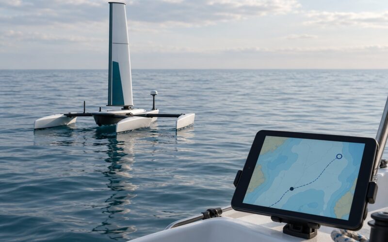
Start by finding the antenna height the shore station already has, then add whatever height the robot needs for its Fresnel requirement at your planned distance. For a typical shore mast, a robot antenna somewhere between 10 and 20 ft above the water is usually enough to clear the zone and keep the mast light. Confirm it with a measured test at two heights before you commit.
What to Do First
Measure the two antenna heights you have now, run them through the horizon formula, and write the ceiling on a piece of paper. If that ceiling sits well beyond the distance you actually need, stop looking at masts and go fix the feedline instead.
If the ceiling is short of the distance you need, make one controlled change, ideally a metre of extra height or a better mounting point at the same height, and log signal strength and delivery ratio before and after. One measured comparison tells you more than a week of speculation, and it costs almost nothing.
Rechecked for 2026.