To build a digital compass for a boat, you need three things: a three-axis magnetometer, a microcontroller, and tilt compensation in the firmware. The sensor measures the Earth’s magnetic field, the accelerometer tells it how far the boat is heeled or pitched, and software combines the two into a heading that stays honest when the hull leans over. Budget a weekend for the wiring, a couple of evenings for calibration, and a day for mounting and sealing. Skipping the calibration is the reason most of these projects sit on a bench looking fine and then read 20 degrees wrong the moment the boat starts moving.
Most forum answers stop after the wiring diagram, so this guide goes further. It covers the mounting rules that keep the sensor away from engines and batteries, the hard and soft iron calibration routine step by step, 12 V marine power conditioning, and how to check your finished compass against a reference instead of trusting it. Where a rule comes from a class association or a builder who has done it on real water, I say so.
Table of Contents
- What You Need
- Step-by-Step: How to Build a Digital Compass for a Boat
- Common Mistakes
- Frequently Asked Questions
- Can I build a digital compass for a boat with an inexpensive magnetometer module?
- How far should a compass sensor be mounted from motors, batteries, and wiring?
- Does a digital compass for a boat need a correction for magnetic declination?
- Do I need to calibrate the compass every time I turn it on?
- Can a magnetic digital compass work reliably on a small autonomous boat?
- Start With the Sensor and the Mount, Not the Code
What You Need
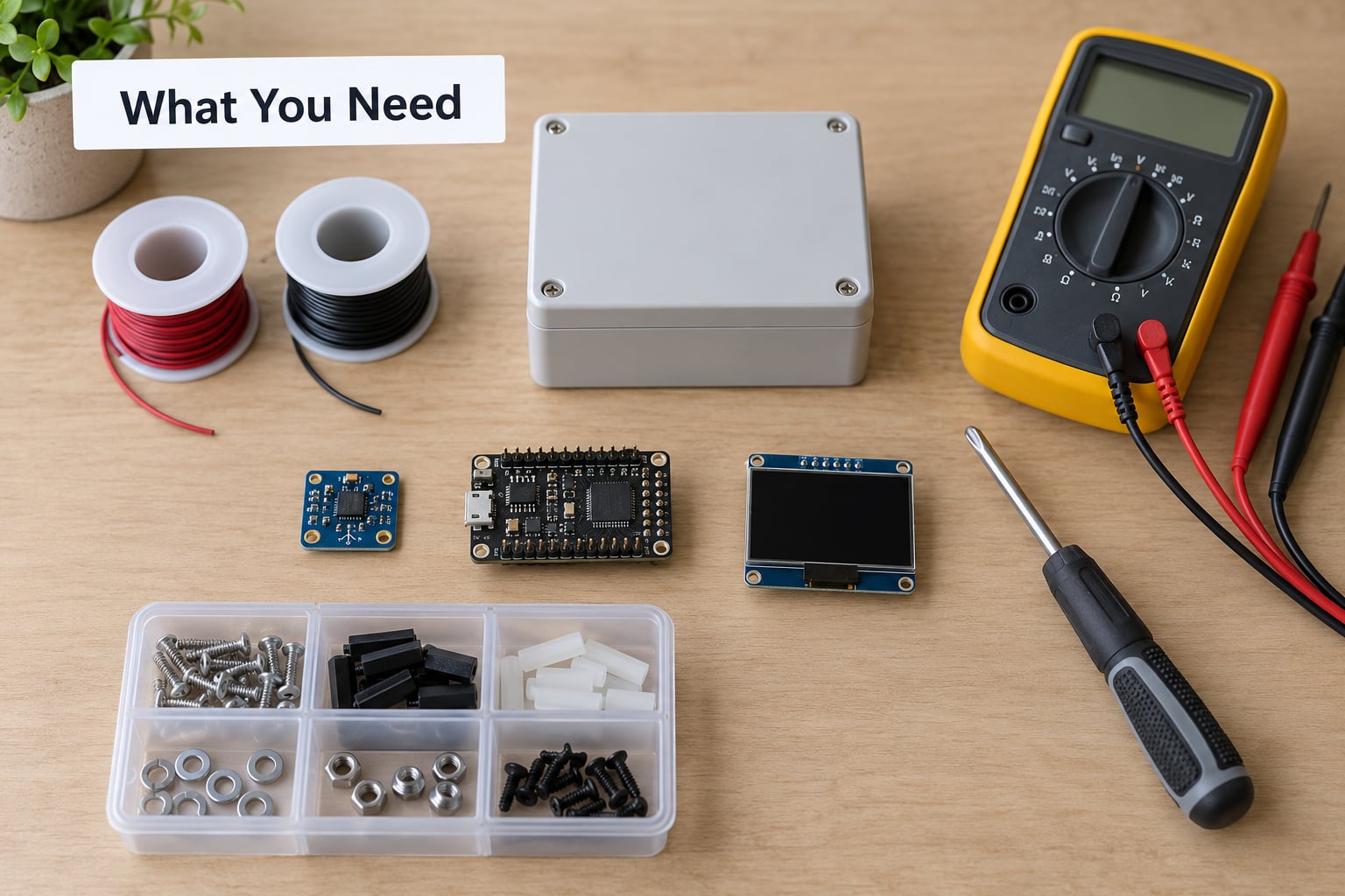
A working build fits in one small box and needs about fifteen parts. None of them is expensive individually, and the total cost of a proper instrument is a fraction of a certified marine compass, which is the whole point for a project boat or an autonomous surface vessel.
The sensing and computing parts
- Magnetometer module, 1. A 9-axis IMU that contains a 3-axis accelerometer, a 3-axis gyroscope and a 3-axis magnetometer. This is the minimum useful sensor because a compass with no accelerometer cannot compensate for heel.
- Microcontroller, 1. An ESP32 is the common pick: it has two I2C buses, plenty of GPIO, Wi-Fi for logging or a dashboard, and enough flash to hold calibration coefficients. An Arduino Nano or Mega works too, with less convenience.
- Display, 1. A 0.96 or 1.3 inch I2C OLED, a small character LCD, or a 2.4 inch TFT if you also want heel, pitch and a heading rose. Night-friendly red backlighting matters more than most people expect on a small boat.
Power and protection
- 12 V to 3.3 V regulator, 1. A buck converter rated for continuous current well above your load, with a common ground. A linear regulator wastes power as heat; a switching buck module is quieter thermally and adds switching noise you may have to filter.
- Inline fuse, 1. Sized to the regulator’s input current. A short in a damp enclosure on a live boat circuit should blow a fuse, not a trace.
- Schottky diode, 1. for reverse-polarity protection on the supply feed.
- Bulk capacitor, 1. around 470 microfarad across the logic rail, plus a 0.1 microfarad ceramic decoupling capacitor at the sensor.
Mechanical and sealing
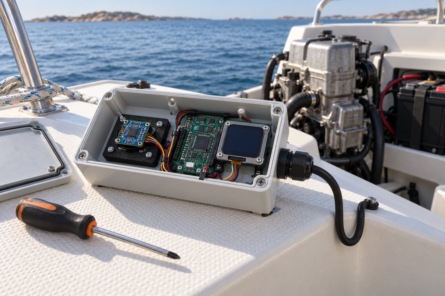
- Sealed enclosure, 1. A polycarbonate or ABS box rated IP67 or better, with a cable gland. A hobbyist box with a clip lid will fill with condensation within weeks.
- Vibration-isolating pad, 1. A small piece of closed-cell neoprene or a marine isolator between the sensor board and the enclosure base.
- Corrosion-resistant hardware. Stainless steel screws, ideally A2 or A4. Standard steel fasteners near a magnetometer are both a corrosion risk and a source of the hard iron offsets you will spend an evening calibrating out.
- Drip loops and strain relief, a small pack of adhesive cable clips, and marine-grade sealant.
Tools
A multimeter, a soldering iron, side cutters, a small screwdriver set, heat-shrink tubing, and a length of screened or twisted pair for the sensor run. Add a phone with a magnetometer app or a handheld magnetic compass for the accuracy check later, and a spirit level for setting the mount square before you seal it.
How to choose the sensor
Buy the module, not the bare breakout board, unless you enjoy soldering fine-pitch pads. A module gives you a regulator, level shifting and a labelled header, and most are already calibrated to a usable range of plus and minus 8 gauss, which covers the Earth’s field of roughly 25 to 65 microtesla with headroom. Check three things on the datasheet before you buy: the supply voltage, the I2C address, and whether the magnetometer is a separate chip on a shared bus with the accelerometer. If the two share an I2C address, you need a multiplexer or a sensor with a fixed address, and that is where first-time builds get stuck.
Step-by-Step: How to Build a Digital Compass for a Boat
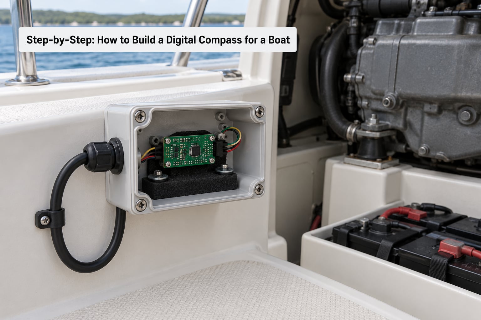
The build runs in seven stages, and each one has a clear signal that it worked. Do them in order and the calibration step goes quickly, because you will be calibrating a finished, mounted unit rather than a loose board on a workbench.
1. Plan the Compass for Marine Use
Start by deciding what the compass is for, because that fixes the update rate, the power budget and where the sensor can physically live. A heading readout for a small sailboat needs about 5 to 10 updates per second and can average aggressively. An autopilot heading-hold loop wants 10 to 20 updates per second with less smoothing, because lag in the loop turns into oscillation at the helm.
Power is the constraint people forget. A marine electronics bus runs on 12 V and swings hard every time the engine starts, so the compass runs from a regulated branch, not from a battery terminal. Budget roughly 60 to 150 milliamps for an OLED or small TFT, depending on backlight. A 2000 mAh lithium pack will run something like this for a weekend of sailing, which is why so many autonomous surface vessel projects use USB power banks and a small solar panel.
Mounting location is the decision that matters most, and it is constrained by physics. The sensor measures a few tens of microtesla, while a starter motor, a 200 amp alternator and a bank of lead-acid batteries produce fields orders of magnitude stronger, right at the frequencies a magnetometer cannot distinguish from the Earth. Sensible defaults, and the reasons behind them:
- At least 1 metre from any engine, alternator, starter motor, inverter or transformer.
- At least 0.5 metre from batteries, heavy current cables, shore power supplies and high-current switching.
- Away from stainless steel hatches, frames, chain, anchors, radio antennas and steel rigging, all of which act as fixed magnets or induced soft iron.
- Away from electronics that draw current in pulses: radar, autopilot drives, inverters, LED dimmers, and switching power supplies.
- If none of that is available on deck, mount the sensor on a mast, a pole or a buoyancy pod. The Homebuilt ROV builder hit exactly this wall and solved it the same way, moving the sensor to a buoyancy pod on a tether with silicone damping because it was the one spot on the craft clear of motor interference.
Set a realistic accuracy target. A cheap magnetometer with good calibration and proper tilt compensation lands within 2 to 5 degrees of magnetic north on a small open boat. On a steel or aluminium hull with a lot of structure above the sensor, 5 to 10 degrees is more realistic. Anything finer than that on a home build means you also need a deviation table measured by swinging the boat, and a magnetometer alone will not get you there.
2. Choose and Position the Magnetometer
There are three sensor families, and the choice is mostly about how much tilt compensation you need. A discrete Hall effect sensor outputs one axis or a set of analogue voltages, is cheap, and gives you a heading with no tilt information. It suits a fixed display on a powerboat that stays upright. A 6-axis IMU gives you accelerometer plus gyro and no magnetometer, so it can tell you heel but cannot give you a heading without a magnetometer elsewhere. A 9-axis IMU is the answer for almost every boat, because the three sensors in one package share a coordinate frame and the accelerometer data lines up with the magnetic axes.
Two details catch people. First, the gyroscope in a 9-axis module will drift and, on a boat with steady pitch, can slowly corrupt a naive fusion. Use an AHRS filter such as MadGwick or Mahony, which handles accelerometer, gyro and magnetometer together, rather than hand-rolling an angle integration. Arduino forum builders working on GPS plus magnetometer heading hold tend to reach for the same combination: a u-blox M8N receiver with a magnetometer module and a mature sensor library, rather than a custom fusion.
Second, mark the sensor’s physical orientation before it goes into the box. Draw an arrow on the enclosure lid showing which way the board’s X axis points when the boat is level and facing forward. The heading maths assumes a fixed relationship between the sensor axes and the boat axes, and a board installed 90 degrees out silently reports a heading that is always off by 90 degrees.
On scale range, stick with the widest range the chip offers and calibrate it down. A plus and minus 8 gauss module saturates near a strong engine field, and a saturated reading is a dead reading that no amount of calibration fixes.
3. Wire the Microcontroller and Display
Power the sensor and the display from the regulated logic rail, run a common ground between all three boards, and keep the I2C wires short. Here is a representative connection plan for a 3.3 volt ESP32 with a 3.3 volt IMU module and a 3.3 volt I2C display.
| Module | Pin | Connects to | Notes |
|---|---|---|---|
| 9-axis IMU | VIN | 3V3 rail | 3.3 V module, no level shifting needed |
| 9-axis IMU | GND | Common ground | Star ground at the regulator return |
| 9-axis IMU | SDA | ESP32 GPIO 21 | 4.7 kohm pull-up to 3V3 if the board lacks them |
| 9-axis IMU | SCL | ESP32 GPIO 22 | Same bus, same pull-ups |
| 9-axis IMU | CS or RESET | ESP32 spare GPIO | Hold low at boot if the address is not fixed |
| OLED or TFT | VIN | 3V3 or 5 V per module | TFT panels often want 5 V and 3.3 V logic |
| OLED or TFT | SDA / SCL | Same I2C bus | Works when the two addresses differ |
| Regulator | VIN | Fused 12 V branch | Fuse, then reverse-polarity diode, then regulator |
| Regulator | GND | Boat ground at one point | Prevents a parallel ground path through the hull |
The voltage warning matters. A 5 volt magnetometer module driving its SDA and SCL lines into a 3.3 volt microcontroller input can damage the pin, and it does not fail cleanly. Options in order of preference: use a 3.3 volt sensor, add a bidirectional level shifter on the two bus lines, or power the sensor from 5 V only if its output pins are open-drain with pull-ups you move to 3.3 V yourself. Never tie 5 V to an ESP32 input to make it work.
Route the sensor cable away from the motor and alternator cables rather than alongside them, and twist signal with ground where you can. Keep the run under 30 cm inside the enclosure if possible, and secure it with a cable clip so vibration cannot tug on the solder joints, which is the usual cause of intermittent dropouts on a heeling boat.
4. Add Filtering and Power Protection
Raw magnetometer data on a working boat is noisy. Engine harmonics, the alternator and even the boat’s own movement in a swell push jitter into the reading, and unfiltered that jitter shows up as a twitching needle and a noisy autopilot input. Three layers of filtering fix most of it.
The first is oversampling at the sensor. Read the magnetometer several times per display update and average the X, Y and Z values. A magnetometer supports several output rates, so setting it to its highest data rate and averaging in software is cheap and effective.
The second is a circular low-pass filter on the heading itself, not on the raw axes. Filtering X and Y independently is the classic mistake, because it distorts the vector and introduces a heading error. Apply the filter to the angle, taking the shortest path around the circle so 359 degrees does not get averaged with 1 degree into zero. A coefficient between 0.1 and 0.3 gives a response fast enough for a helm and smooth enough to read.
The third is a deadband on the display. Redraw the number only when the filtered heading changes by half a degree or more. At 10 updates per second that halves the display traffic and stops the digits flickering while the boat sits at rest.
For power, the sequence on the 12 V feed is: fuse, reverse-polarity diode, then the buck regulator, then a bulk capacitor. Add a 0.1 microfarad ceramic right at the sensor’s power pins because switching regulators and long cable runs produce exactly the low-level noise the magnetometer picks up as heading error. Give the compass its own fused branch rather than tapping it off a navigation light circuit, and give that circuit its own return to the battery negative so current does not flow through the hull between the compass and its supply.
Decide what happens when power sags. On an ESP32, a brownout resets the board and you lose your calibration unless you stored it in flash. Write the coefficients to non-volatile memory after every successful calibration run, and on boot skip recalibration if the stored values are present. That single line of code is the difference between a five-minute restart and a full calibration routine at anchor.
5. Program the Heading Calculation
The firmware is four blocks: read the sensors, apply the calibration coefficients, compute the tilt-compensated heading, and render it.
First, calibration. The raw reading gets corrected by subtracting the hard iron offset vector and dividing by the per-axis scale factors that you measured in step 6:
xc = (x - bx) * sx
yc = (y - by) * sy
zc = (z - bz) * sz
Second, orientation. The accelerometer plus a long-term gravity filter gives you roll and pitch. With those you can rotate the corrected magnetic vector into a level frame so the tilt is removed mathematically instead of being ignored:
Xh = xc * cos(pitch) + zc * sin(pitch)
Yh = xc * sin(roll) * sin(pitch) + yc * cos(roll) - zc * sin(roll) * cos(pitch)
Third, heading. Two arctangents and you are done:
headingMag = atan2(-Yh, Xh)
Convert to degrees and wrap into 0 to 360. The sign on the Y term depends on which way you defined forward, so check it once against a known heading and flip the sign if the reading is mirrored. Then add declination to get true heading:
headingTrue = (headingMag + declination + 360) % 360
Magnetic heading points at magnetic north. True heading points at geographic north, and the difference between them is the local magnetic declination, typically a few degrees east or west depending on where you are. Look up the value for your area from a current magnetic declination source, store it as a constant in the firmware, and remember it drifts slowly over years, so make it a setting you can change rather than a hardcoded number buried in the display routine. If the compass feeds an autopilot or a chartplotter, output both over NMEA 0183 in the HDG sentence and let the consumer apply its own offset.
One term people confuse constantly. Declination is geographic and the same for every boat at a given location. Deviation is the error the boat’s own steel and electrical gear causes, and it is specific to your hull and your equipment layout. Calibration reduces deviation. It does not touch declination, and no amount of calibrating fixes a compass that has never had declination added.
A flat-mounted sensor on a small boat that rarely heels much can get away with a simple atan2 on X and Y, with no tilt maths. The moment the boat is heeling past 20 degrees or pitching in a seaway, the Z axis carries part of the Earth’s vertical field into the horizontal plane and the heading error grows with the angle of heel. If you can only include one advanced feature, make it this one. A heel angle readout alongside the heading is a good sanity check that the tilt compensation is working, because a bad roll estimate shows up as heading error that grows exactly as the heel grows.
6. Calibrate the Compass
Calibration is the step that turns a plausible number into a correct one, and it is the step most builds skip. It comes in two parts. Hard iron distortion is a constant offset from permanent magnets and magnetised steel: bolts, a speaker magnet, a tool left in the boat, the transducer on an autopilot. Soft iron distortion comes from unmagnetised ferrous material, which bends the field into an ellipsoid instead of a sphere. Correcting only one of them leaves a heading that is still wrong, and corrects the two with the wrong maths and leaves it worse.
Here is a repeatable procedure, and it needs the complete unit, mounted, powered and on the boat.
- Remove what you can. Take out loose ferrous items, move phone mounts, speakers, toolboxes and anything magnetic out of the enclosure area. Recalibrate later if you add equipment back, because each change moves the offsets.
- Warm the sensor up. Leave it powered for ten minutes. Magnetometer offset drifts with temperature, and calibrating cold then running hot gives an error that changes through the morning.
- Clear the deck. For the full ellipsoid method, rotate the entire boat through orientations, which is easiest at a quiet dock. The figure-eight method only needs the sensor itself, which is better if the enclosure is already sealed.
- Collect at least a few hundred samples. For the figure-eight, tumble the sensor through a figure-eight path in three axes, reorienting the board every few seconds so no single orientation dominates. For the ellipsoid method, hold the boat still while slowly turning it through yaw, then roll and pitch through as many attitudes as you can reach, sampling continuously.
- Fit the model. The hard iron offset is the centre of the cloud of raw readings, taken as the mean of X, Y and Z. The soft iron correction is the per-axis scale needed to turn that cloud back into a sphere.
- Store the coefficients in flash on the microcontroller so they survive a power cycle, and print them so you can note them down.
- Verify. With the unit installed, slowly swing the boat through a full circle on the dock and watch the heading. It should sweep smoothly through 360 and return to where it started. Repeat while the engine is running and while it is off, and compare. A large difference between the two means the sensor is still too close to an interference source, and no amount of recalibration in that position will fix it. Move the sensor first, then calibrate again.
Repeat the whole routine if you move the sensor, add a new piece of equipment, or change the boat’s electrical load significantly. For a boat that lives under a dock and runs on a battery, twice a season is plenty.
7. Mount, Seal, and Test the Unit
Mount the unit rigidly but isolated. Screw the enclosure to a bulkhead, console or deck, and put a neoprene pad between the sensor board and the enclosure base so engine vibration does not shake the element itself. A fixed mount is what lets the offset-and-scale coefficients stay valid: if the sensor moves relative to the boat, the whole calibration shifts.
For sealing, use an IP-rated enclosure with a cable gland rather than tape and hope. Mount the gland at the bottom, not the top, so any water that gets in drains out. Dress the cable as a drip loop: come out of the gland, drop below it, then rise to the panel, so water runs off instead of following the conductor. Bed the gland in marine sealant, not silicone. Inside, secure the board on standoffs so it cannot rattle, and keep the sensor away from the power components in the same box; on a small build, the switching regulator and the magnetometer sitting 5 cm apart is a real source of heading noise.
Set the display angle so it is readable from the helm position, and test the backlight at night before you seal the case. Add the forward arrow to the lid while it is still open.
Test in three stages. On the bench, confirm the reading changes smoothly as you rotate the unit and that the tilt compensation does something when you tip it through 90 degrees: the heading should stay roughly constant. Dockside, compare against a handheld magnetic compass at several points around a full circle, and note the difference at each one; a constant offset is magnetic north versus true, so add declination, while an error that varies with boat angle is deviation and means recalibrate. Underway, run the same comparison with the engine at cruise, and again with a load of different people aboard, since the steel belt buckles on a person’s belt buckle can be exactly that kind of load. A compass that is only ever checked on a calm dock at anchor has not been tested.
Before you rely on the result, check the class rules. Some racing associations prohibit electronic compasses outright, and others restrict where a compass may be mounted. A discussion on sailingforums.com makes the point plainly: the class rules in question state that electronic and digital compasses are prohibited, with only one compass permitted. Check your own class before you cut a hole in a bulkhead.
Common Mistakes
Almost every failed build comes down to one of the nine issues below. Work down the table from the symptom rather than guessing at the code.
| Symptom | Likely cause | Fix |
|---|---|---|
| Heading is off by a fixed amount on every heading | Declination not applied | Add the local magnetic declination in software; do not try to absorb it into calibration |
| Error grows as the boat heels | No tilt compensation, or roll estimate is poor | Use the accelerometer axes in the heading maths and verify the roll readout against a clinometer |
| Reading jumps when the engine starts or revs | Magnetic interference from alternator, starter or a high-current cable | Move the sensor at least a metre away, reroute the cable, and calibrate with the engine running |
| Heading is wrong by tens of degrees in some directions only | Soft iron distortion, or calibration done on a loose board | Redo the ellipsoid calibration with the unit mounted, and fit per-axis scale |
| Heading is constant and obviously wrong after install | Sensor board mounted 90 or 180 degrees out | Mark the forward axis and swap the orientation offsets in firmware rather than rotating the board again |
| Bus errors or dead readings, sensor works on the bench | Voltage mismatch, long I2C run, or missing pull-ups | Match supply voltages or add a level shifter, keep I2C under 30 cm, and fit 4.7 kohm pull-ups |
| Heading jitters and the digits flicker | No filtering, or filtering the X and Y axes separately | Oversample, then low-pass the heading angle around the circle and add a half-degree display deadband |
| Reading drifts over a few minutes, then a number of tens of degrees appears | Sensor saturating near the engine | Use the widest measurement range, reduce the scale setting, and move the sensor away |
| Works until it rains, then fails intermittently | Condensation inside the enclosure bridging the board | Use an IP-rated box with a bottom cable gland, add conformal coating on the board, and include a vent or desiccant |
Three habits keep a build honest. Write down the mounting location, the sensor orientation and the calibration coefficients in a comment at the top of the firmware, because you will move the unit eventually and want to know what changed. Log the heading to a serial line or an SD card during sea trials so you can compare a bad patch of data with what the engine was doing. And keep a certified magnetic compass on board regardless, since it needs no power, no calibration and no firmware, and it is the reference you will use when the electronics misbehave.
One more thing builders report: a compass small enough to hide in a footbrace or a console pocket is asked for constantly on sailing forums and in r/sailing threads, and the size question is decided by the enclosure, not the sensor. Choose a box you can seal first, then fit the board inside it. A working instrument in a slightly larger box beats a beautiful one in a housing that will not survive a season.
Frequently Asked Questions
Can I build a digital compass for a boat with an inexpensive magnetometer module?
Yes, for a small open boat on a calm or moderate day. An inexpensive three-axis magnetometer with a working accelerometer will read within a few degrees of magnetic north once hard and soft iron calibration is done properly and the sensor sits away from the engine. Expect less on a steel hull with equipment mounted above the sensor. Accuracy below about two degrees needs a deviation table measured by swinging the boat.
How far should a compass sensor be mounted from motors, batteries, and wiring?
Keep it at least one metre from the engine, alternator, starter motor and any inverter, and at least half a metre from batteries and heavy current cables. Large steel items like hatches, frames and anchors also distort the field, so keep the sensor away from them too. If there is no clear spot on deck, mount it on a mast, pole or buoyancy pod, then calibrate in its final installed position.
Does a digital compass for a boat need a correction for magnetic declination?
Yes, if you want true heading. A magnetometer gives you magnetic heading, which points at magnetic north. True heading points at geographic north, and the difference is the local magnetic declination, usually a few degrees. Add it in software to get a true reading, and output both if the compass feeds a chartplotter or autopilot. Declination is separate from deviation, which is the error caused by the boat’s own steel.
Do I need to calibrate the compass every time I turn it on?
No. Calibrate after installation, after moving the sensor, after adding new equipment near it, and a couple of times a season. Store the hard iron offsets and soft iron scale factors in flash so they survive a power cycle, then skip calibration at boot. Do let the sensor warm up for about ten minutes before calibrating, because its offset drifts with temperature and a cold calibration will not hold through a warm morning.
Can a magnetic digital compass work reliably on a small autonomous boat?
It can, and builders of autonomous surface vessels routinely pair an ESP32 with GPS and a digital compass for navigation. The compass is the heading source for turns and for heading-hold loops, so it needs tilt compensation, filtering, and a fixed mount away from thruster wiring. Keep a magnetic compass aboard as a sanity check, and remember that some race classes prohibit electronic compasses, so check the rules before racing.
Start With the Sensor and the Mount, Not the Code
Building a digital compass for a boat is mostly two decisions, and both come before any firmware: pick a 9-axis sensor with a readable display and a sealed enclosure, and find a mounting spot a metre clear of the engine, batteries and steel. Once the box is sealed and fixed in place, the wiring is an afternoon, the heading maths is an evening, and the calibration is a couple of hours at the dock with the boat swung through a full circle. Do it in that order and the instrument works on the first trip out.