Planning a waypoint route for a drone boat means turning a survey goal into an ordered list of positions the vessel can actually reach, hold, and return from within its energy and turning limits. The route is not the straight line between two map pins; it is a sequence of legs sized for your vessel’s speed, turn behaviour, depth, and the water you are crossing.
The whole job takes an afternoon at a desk for a first mission, plus a short on-water trial. Most of that time goes into the chart work and the energy budget, not the software. Get those two right and the waypoint list practically plans itself.
Table of Contents
- What You Need
- Step-by-Step: How to Plan a Waypoint Route for a Drone Boat
- 1. Define the mission and operating limits
- 2. Choose a suitable chart and coordinate system
- 3. Identify hazards and exclusion areas
- 4. Plot waypoints and calculate the route track
- 5. Check endurance, timing, and failure paths
- 6. Validate the waypoint route before launching
- 7. Test and update the waypoint route in stages
- Common Mistakes
- Frequently Asked Questions
- Conclusion
What You Need
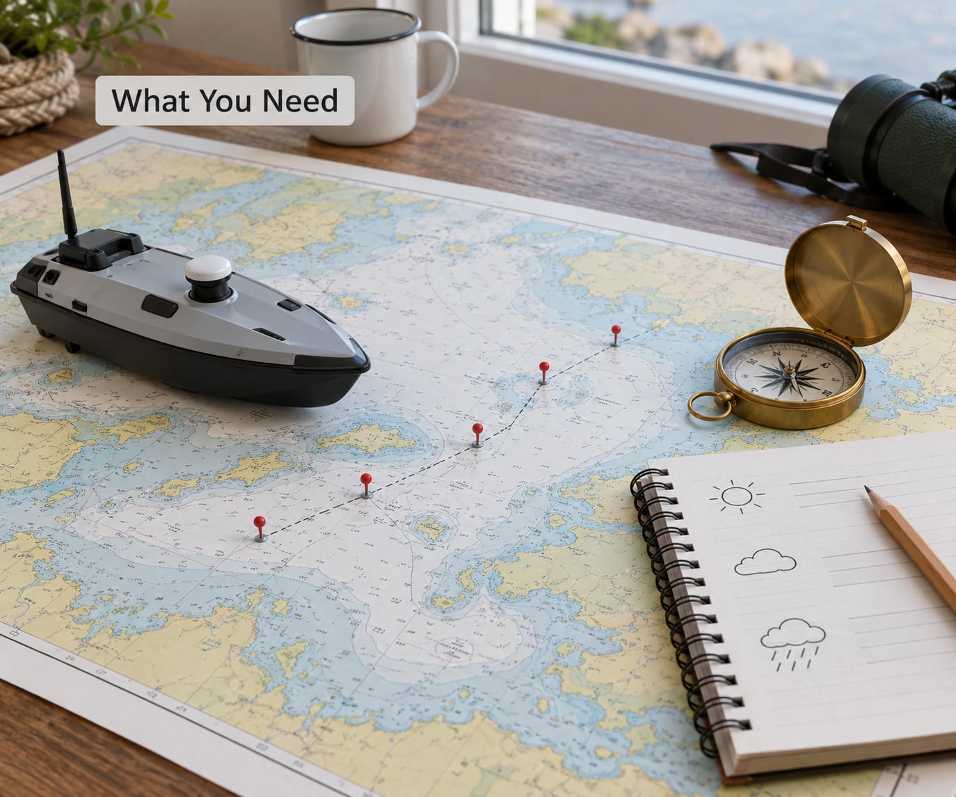
Collect these before opening any ground control station. Planning a route with missing inputs is guesswork dressed up as engineering.
- Mission objectives. The area to cover, the pattern needed, the positional accuracy the data must meet, and the time of day the work must happen.
- Vessel specifications. Top speed, cruise speed, turn radius or turn-in-place capability, draft, battery capacity, and measured endurance under load.
- Current charts. A paper or digital nautical chart at a scale larger than the operating area, plus any local notice to mariners.
- Weather and current data. Forecast wind speed and direction, wave state, tidal range and timing, and current set and drift for the operating window.
- Navigation rules. Traffic lanes, port approaches, speed-restricted zones, and protected or swimming areas within range of the planned track.
- A ground control station. QGroundControl, Mission Planner, or ArduPilot Mission Designer, running on a laptop at the desk rather than in the field.
- Recovery equipment. Spare batteries, a manual RC controller with a working fail-safe switch, a charger that runs on shore power, and something to tow the boat home with.
Measure endurance yourself rather than trusting a datasheet. Run the boat loaded with its normal payload at cruise speed until the battery reaches your reserve threshold, and write down the minutes. That number sets every leg length in the route.
Step-by-Step: How to Plan a Waypoint Route for a Drone Boat
Each stage produces one written decision. If you cannot write the decision down, the stage is not finished. The order matters because each stage constrains the next one.
1. Define the mission and operating limits
Write down the survey purpose, the required coverage area, acceptable positional error, and the duration the boat must stay out. Then set the limits that will stop the mission: maximum speed, minimum battery reserve, maximum wind and wave conditions, and the specific conditions that trigger an abort.
Two numbers decide everything downstream. Positional error determines how precisely the boat must hold a line, and duration determines how many legs fit in the energy budget. A water-quality sampling transect tolerates a few metres of error; a bathymetry survey with narrow pass spacing does not.
Record: area boundary, mission duration, positional tolerance, abort criteria.
Check: another person reading your page can state when to abort without asking you.
2. Choose a suitable chart and coordinate system
Use the largest-scale chart that still covers the whole operating area, and confirm the chart edition and its datum before you type a single coordinate. Datum matters more on a tidal water mission than most people expect: two charts of the same harbour can disagree about where a wall is by more than your position tolerance.
Convert every coordinate in one pass, to one format, from one source. Boats using ArduPilot Rover firmware take latitude and longitude in decimal degrees; make sure your chart software is not mixing degrees-minutes-seconds with decimal degrees somewhere in the middle of the file. Check the plotted start point against a known landmark, such as a jetty corner, before generating anything.
Record tidal height at the chart datum for the planned launch time. You will need it later to correct depth readings captured at a different tide state.
Record: chart number and edition, datum, coordinate format, tidal height at launch.
Check: the start point lands within a few metres of a landmark you can identify on the water.
3. Identify hazards and exclusion areas
Work outward from the operating area in three rings. First the water itself: shoals, rocks, submerged obstructions, shallow bars, and anything that grounds the boat at the tide state you expect. Second, the fixed exclusions: ports and harbour approaches, traffic lanes, construction zones, cables, aquaculture installations, and swimming areas. Third, the temporary and environmental ones: exposed fetch, current lines, kelp or weed beds, and floating debris.
Floating debris deserves more weight than it gets. In one ArduPilot field report, a 1.6 km lake mission ended with the boat hitting three separate floating obstacles on open water. The survey grid you plot is a corridor through that water, so treat the corridor, not just the survey area, as the thing you are planning.
Record: a hazard list with a clearance distance for each entry, and a minimum depth allowance for the whole corridor.
Check: every leg of the route stays clear of every listed hazard by its clearance distance at the expected tide.
4. Plot waypoints and calculate the route track
Start with four kinds of point: the launch point, the mission points, the return point, and at least one contingency point you can divert to. Then fill in the mission points using a pattern that suits the job. A serpentine or lawnmower grid suits bathymetry and wide-area coverage. A single corridor of cross-track legs suits a transect or water-quality line. An expanding square suits a search with a point of interest that is not yet located.
Now check the geometry against the vessel. A hull with differential thrust can rotate on the spot, so it can make a tight turn between closely spaced lines. A single-thruster hull must swing through an arc, so the minimum achievable spacing is set by its turning circle, not by the sensor. A wide-beam echosounder forces a similar limit from the other side, because the swath has to fit between lines.
Compute the line spacing from the sensor first, then confirm the vessel can physically turn to reach it. In practice, operators surveying multi-acre lakes up to about 7 m deep report that pass spacing of roughly 4 m at around 1.25 m/s is a workable baseline with a wide-beam chirp unit. Tighter spacing still misses bottom in places; wider spacing and you have data you cannot join into a map.
Watch the turns rather than the straight legs. A long leg at cruise speed is easy. A short leg immediately after a turn means the boat is still rotating when it reaches the next point, which produces a curved transition and a data gap exactly where the grid is tightest.
Record: waypoint list with per-leg speed, leg length, heading, and turn allowance.
Check: no leg requires a course change the hull cannot physically complete at the commanded speed.
5. Check endurance, timing, and failure paths
Add up every minute in the mission: transit to the survey area, each survey leg, the turns, the manoeuvring and settling time at each end of a line, data capture time, transit home, and the reserve. Compare the total against the endurance you measured, not against the battery label.
Set the reserve deliberately. A common planning rule is to plan the mission around roughly 70% of usable capacity, leaving the rest for current against you, a wind shift mid-mission, waiting out traffic, and one failed start. If your mission only fits inside 85% of capacity on a calm day, it does not fit on the day you actually need it.
Add current to the maths. Ground speed over the bottom is the vector sum of your commanded speed through the water and the set and drift. A 1.25 m/s boat in a 0.5 m/s foul current makes 1.25 m/s one way and about 0.75 m/s the other, so the outbound legs finish faster than the inbound ones and your whole timing budget shifts.
Then write the failure paths. What does the boat do if telemetry drops? If it loses GPS fix? If the wind pushes it outside the corridor? If it arrives at a waypoint that is now blocked by debris? Decide the action for each, and set the abort thresholds in numbers rather than judgement.
Record: total mission minutes, battery at mission end, abort thresholds, failsafe actions.
Check: the route still completes with one leg repeated, still inside the energy budget.
6. Validate the waypoint route before launching
Compare the planned route against what the boat actually did on your last trip. Every number on the plan should be traceable to something you measured: cruise speed from a logged run, turn radius from a dock test, positional error from a dataflash log, endurance from a loaded endurance run.
Simulate the failures rather than just imagining them. Walk the route on the ground control station map and ask what happens if the boat misses waypoint nine by 30 m, if it arrives at waypoint four on the opposite heading, if the tide is two hours off your assumption. Any of those that has no safe answer is a gap in the plan, not in the boat.
Set the safety layers before you go. A geofence keeps the vessel inside your corridor and outside restricted water. Return to launch gives it a default ending. The failsafe action decides what happens when it cannot hear you, and for a boat returning to a launch point it cannot reach, continuing or holding is often safer than trying to get home.
Brief the launch team. Everyone on the boat should know who calls the abort, what the abort action is, and where the manual controller switch is. Then write the abort criteria down: battery below a stated level, wind above a stated speed, GPS fix count below a stated number, or any contact with an unidentified object.
Record: geofence boundary, RTL point, failsafe actions, abort criteria, team assignments.
Check: an untrained person can read the abort card and take the right action.
7. Test and update the waypoint route in stages
Do not launch the full mission first. Run a bench check with the boat on blocks, confirming that the mission file downloads from the autopilot and matches what you uploaded. On ArduPilot Rover the upload uses the MAVLink mission protocol, with the mission count and items sent before the request to set the current item, and a download-and-compare step catches most transfer failures before they happen on the water.
Then run a short water trial: launch, navigate to the first mission point, hold station, return, and land. Watch how the hull behaves in the actual current. Compare the achieved track against the planned legs and note the offsets.
Expand the route in stages from there. Add one leg, fly it, check the data, add the next. Each stage logs what you actually observed: heading error, cross-track error, speed achieved against speed commanded, energy used per hour, and whether the turns came out clean.
Revise the route from those logs, not from intuition. If cross-track error is consistently high on one heading and low on the reciprocal, the fix is current compensation or a slower speed, not a wider corridor. After the first full mission, re-fly a section at lower speed with the passes rotated 90 degrees as a cross-check on the data.
Record: per-stage log with achieved versus commanded speed, cross-track error, energy per hour.
Check: the revised route, not the original, is what gets uploaded for every mission.
Common Mistakes
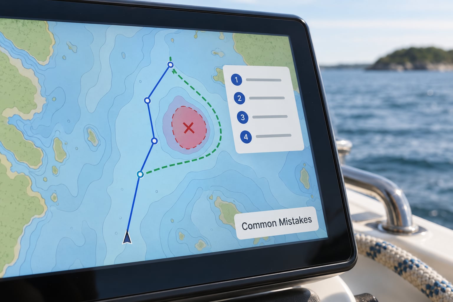
Drawing the route on an aerial satellite image. Map tiles are not charts. They do not show the datum, the shallow bar that dries at low water, or the moored fishing fleet. Plan on a chart and use the satellite view only to sanity-check landmarks.
Leaving sensor factory defaults in place. The echosounder commonly used on small survey boats ships with a 10 m range default. On a lake deeper than that, the sounder silently returns nothing useful and you discover it after the flight. Set range, gain, and logging rate before the first mission, not after.
Setting line spacing from the sensor name instead of the swath. Compute the spacing from the actual beam width at the depth you expect, then widen it for the boat’s turning circle. Widening the beam without widening the spacing leaves uncovered bottom between lines.
Ignoring thruster wash and aeration near the transducer. Prop wash aerates the water directly under the sensor and corrupts depth readings along a straight line. Thrusters mounted near the surface also pick up floating debris, which puts a log in the water in front of you.
Planning for a wind direction that will not exist. Windage on a surface vessel is significant, and a route planned for a following wind becomes a crab and a return leg into a beam sea. Plan the return against the forecast, and shorten the mission if the forecast disagrees with the plan.
Returning home as the loss-of-signal action. If the launch point is up a channel, behind a bridge, or on the wrong side of the traffic, the return-to-launch failsafe drives the boat somewhere worse. Continuing or holding is often the right default on water.
Skipping the download-and-compare verification. A partially transferred mission can leave the autopilot running a shorter route than the one you planned. Downloading the mission back and comparing it to the file you uploaded takes a minute and catches the whole class of problem.
Before each launch, run this short check: chart edition and datum confirmed, tide height at launch written down, hazard clearance verified against the lowest expected tide, geofence set, failsafes configured and tested, abort card filled in, spare battery charged, manual controller confirmed working. If any line is blank, the route is not ready.
Frequently Asked Questions
How far apart should survey waypoints be on a drone boat?
Set the spacing from your sensor’s swath at the depth you expect, then confirm the vessel can turn to reach it. Field reports on multi-acre lakes up to about 7 m deep put roughly 4 m pass spacing at around 1.25 m/s as a workable baseline with a wide-beam chirp echosounder. Spacing tighter than the swath leaves gaps you cannot fill later, and a hull that cannot complete the turn will round the corners instead of tracking the line.
Can an autonomous surface vessel turn in place?
It depends on the propulsion. Differential-thrust hulls with two independently controlled thrusters can rotate on the spot, which lets them track closely spaced survey lines. A single-thruster or single-screw hull must swing through an arc, so its minimum achievable line spacing is set by the turning circle at the commanded speed. Check the manual for your specific hull, then measure the turn in open water before you commit it to a route.
How do you plan a boat route around wind and current?
Plan against the return leg, not the outbound one. A 1.25 m/s boat in a 0.5 m/s foul current makes good roughly 1.25 m/s one way and 0.75 m/s the other, so timing and battery both change. Add windage on top, since a surface hull carries sail area above the waterline. Write current set, drift, forecast wind direction, and tidal state into the mission sheet for the actual launch window, then shorten the mission if conditions exceed your abort criteria.
Does QGroundControl work with ArduPilot Rover?
Yes. QGroundControl works with ArduPilot Rover hardware and is one of the two most common ground control stations for autonomous surface vessels, the other being Mission Planner. QGroundControl is cross-platform and its mission planner handles survey grids, geofence, and rally points. Mission Planner is Windows-only but adds stronger parameter and dataflash log analysis, which matters when you are troubleshooting a mission that failed partway through.
How do I change a waypoint route last minute?
Edit the route in the ground control station on shore, validate it again, re-upload it, then download it back to confirm the autopilot received the change. Do not hand-fly the new route to build waypoints; nobody should. If the change is only a small deviation, such as skipping a leg around debris, add the replacement points to the existing mission rather than rebuilding it. Never edit a mission while the boat is running it unattended.
How many waypoints can a boat mission hold?
That depends on the autopilot’s storage and firmware rather than on the boat itself, and modern hardware handles mission counts in the hundreds comfortably. The practical limit for a survey is leg length and battery, not waypoint count. Missions that need thousands of points are usually a sign that your line spacing or survey area is wrong. If your lake transect produces more points than you expected, revisit the pattern before adding storage.
Conclusion
Start by writing the mission limits, not the waypoints. Then read the chart for datum and hazards, plot a pattern your hull can actually track, budget the energy with a real reserve, and set the abort criteria in numbers before you leave the desk. Test the route in short stages and let the logs revise it. That sequence is how to plan a waypoint route for a drone boat that finishes, comes home, and produces data you can use.