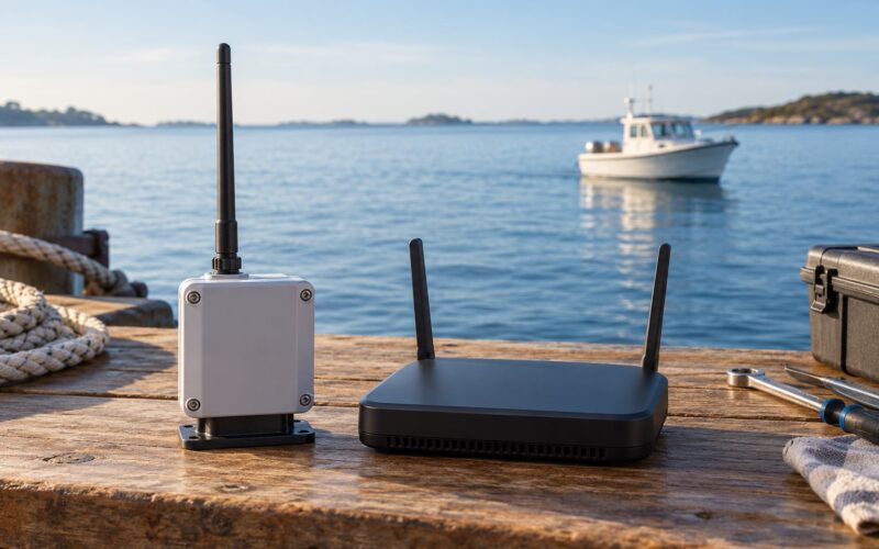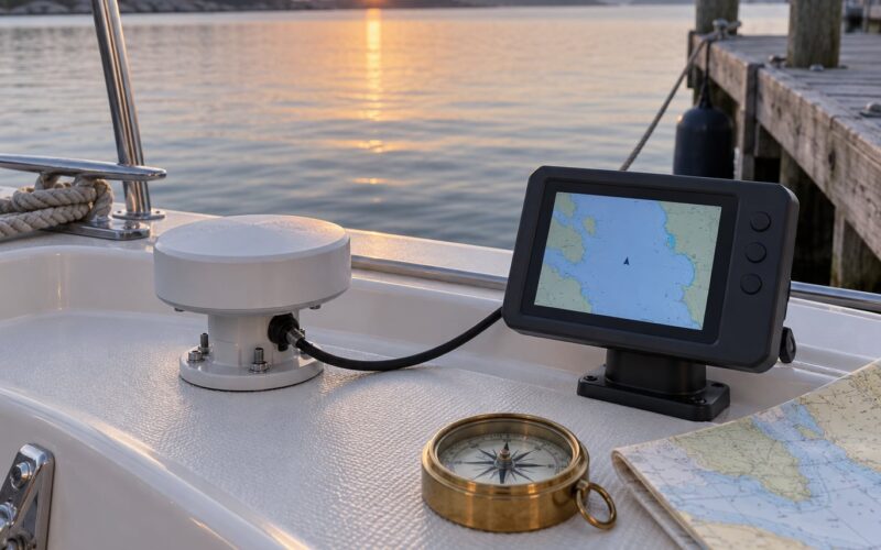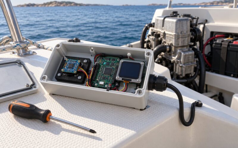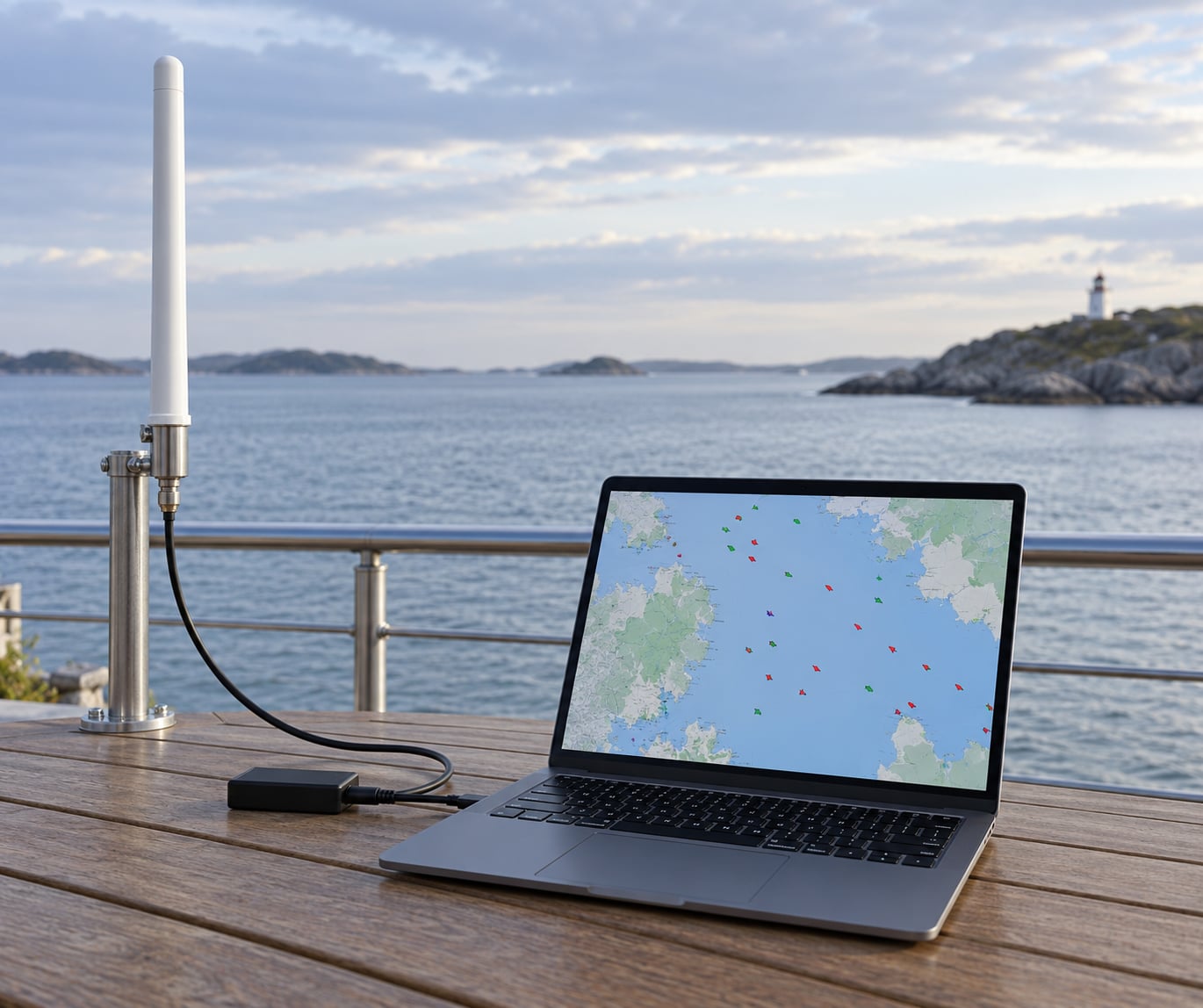
To build an AIS receiver you need four things: an RTL-SDR dongle, an antenna covering the 162 MHz marine band, a computer to run the decoder, and software that turns raw samples into NMEA sentences. Everything below is receive-only, and it works on a laptop or a headless Raspberry Pi.
That is the whole trick. AIS is a broadcast system, so nothing needs to be granted permission before you listen. You put a wideband receiver on two channels, decode the GMSK packets, and suddenly every vessel in line of sight is a marker on a chart with a name, a course and a speed.
It is worth saying plainly what this is not. A receiver listens. A transponder is the opposite device: it broadcasts your own position, needs type approval and a valid MMSI, and belongs on a different build altogether. Search results for this topic mix the two constantly. If you want to be seen, you are shopping for a Class A or Class B transponder, and none of the steps in this guide get you there.
The people building these are usually three groups. Small-boat owners who want a target display without a commercial AIS unit. Researchers and harbour watchers running a shore station to log coastal traffic. And radio hobbyists who want a first serious software-defined radio project that produces something visible on a map within an afternoon.
The r/AIS community frames it the same way: build an inexpensive receiver at home, map the vessels in your area, and hand the data on so the global picture improves for everyone else. That last part is free, and it is the reason your feed is worth having.
One limit up front, because it matters: hobby AIS reception is not a navigation aid. Nothing built from a USB dongle should ever be the thing you steer by.
Last updated: October 2026
What You Need
The build is four components and some wire. Most people spend more time choosing the antenna than the radio, which is the correct order of priorities.
| Component | What to look for | Why it matters |
|---|---|---|
| RTL-SDR dongle | RTL2832U with an R820T2 or R820T21 tuner and a temperature-compensated oscillator | Tunes roughly 24 MHz to 1.7 GHz in one piece, so both AIS channels sit inside one passband. A TCXO version drifts far less than a bare crystal |
| Antenna | A 162 MHz or VHF marine whip, or a 3 dB vertical, with an SMA or N-type connector | AIS is a vertical, line-of-sight system. Antenna height moves the result more than any other choice here |
| RF cable | RG-58 for short runs, RG-213 for longer ones, plus an SMA pigtail if the connectors do not match | At 162 MHz every metre of thin coax costs signal you cannot get back. Under about 5 m of RG-58 is the sensible ceiling |
| Host computer | A Raspberry Pi 4 or 5 on 64-bit Raspberry Pi OS, or any laptop from the last decade | Runs the driver and the decoder. A Pi is the usual choice for an always-on station because it draws only a few watts |
| Power | The official Pi power supply, plus a powered USB hub or a good-quality USB port if a hub is used | Starved USB power is the single most common cause of a dongle that works on one computer and not another |
| Mounting | Mast clamp, stainless fixings, cable ties, drip-loop hardware, self-amalgamating tape | Salt water and UV destroy cable ties and bare steel in a single season |
| Software | RTL-SDR driver, the AIS-catcher decoder, optionally OpenCPN or SignalK on the display side | Turns samples into AIVDM sentences and routes them to a chart or a community feed |
| Optional: uplink | An internet connection, or a 4G router for a remote site | Needed only if you share your feed to a community network |
Yes, you can absolutely use a VHF antenna for AIS, and most existing marine installations already have one. A marine whip is designed to cover 156 to 163 MHz, and both AIS channels sit inside that range, so it works with no modification. A dedicated 162 MHz antenna is shorter and a cleaner match, which matters when you are running a long cable to a mast-mounted dongle.
What you must not use is a cellular or LTE antenna. Those are tuned several hundred megahertz higher, and pairing one with an RTL-SDR at 162 MHz is a mismatch so severe that you will probably conclude the dongle is broken. It is not broken. It is looking at the wrong part of the spectrum.
Which SDR should you buy?
An RTL-SDR is the sensible default, but three other options are worth knowing before you commit.
| Device | Tuning stability | AIS channels at once | Best for |
|---|---|---|---|
| RTL-SDR v4 | Good, with a TCXO | Yes, both | Cheapest way to a working receiver, and the best-supported option in every decoder |
| AirSpy Mini or R2 | Very good | Yes, both | A crowded RF environment, or a site where you want fewer USB resets |
| HackRF One | Good | Yes, wider capture | Experimenting with other services, or multi-channel monitoring. More setup work for AIS alone |
| Dedicated AIS receiver | Fixed and factory set | Yes, both | Plug-and-play use with no driver or tuning work. Less interesting as a build |
Channel coverage is regional rather than universal. The two AIS channels, 161.975 MHz (channel A) and 162.025 MHz (channel B), are the worldwide standard, and a decoder that can only hear one of them will roughly halve what you see. Before buying anything, check the band plan for your region and confirm the receiver covers 162 MHz without an internal filter or preselector blocking it.
Step-by-Step
Here is how to build an AIS receiver in the order that saves the most rework: plan it, mount the antenna, install the radio, tune it, decode it, connect a display, test the range, then make it permanent.
1. Plan the receiver for AIS reception
Decide what this receiver is for before you buy parts, because it changes the antenna and the host. A desk experiment for an hour and an always-on shore station have very different requirements, and the only expensive mistake is building the first one and then wanting the second.
Confirm the channels your decoder will listen on: 161.975 MHz and 162.025 MHz, referred to in most command-line tools as the left and right frequency. A receive-only setup never transmits, so nothing here is capable of interfering with other traffic, and you need no licence of any kind to listen.
Think about indoor versus outdoor at this stage. An antenna behind a window or in an attic loses most of the signal to glass and foil-backed insulation. A coastal site with a clear horizon view will reward an outdoor mast; a flat inland site will rely more on tall traffic passing at distance.
How you know it worked: you can name the two channel frequencies, the intended location, and whether the host is a laptop for testing or a single-board computer for permanent running.
Checkpoint: if you cannot see any vessel traffic from where you sit, stop there. Plenty of people build a perfect receiver pointed at an empty horizon and conclude the electronics are faulty. Look at the view first.
2. Assemble and mount the antenna system
Mount the antenna first and run the cable to the computer, rather than the other way round. Cable length is the expensive thing to change later, and the antenna position is the single biggest factor in what you end up receiving. The communities that discuss this topic agree on this point more than any other.
Connect the 162 MHz antenna to the SDR with the shortest sensible run of coax. Most dongles carry an SMA female socket, so you need an SMA male-to-female pigtail or a short jumper, plus any adapter your antenna connector needs. Bite the coax, keep the run under about 5 m of RG-58, and skip the cheap extension leads that come in a bag of twenty.
Mount the whip as high as you can reasonably get, on a clear pole, with a genuinely unobstructed view of the horizon in the directions you care about. A roof ridge usually beats a wall. A mast top beats a roof ridge.
How you know it worked: the antenna sits above surrounding rooflines, the coax is secured at intervals with proper marine-grade ties, and the connector has a bead of self-amalgamating tape over it.
Checkpoint: every metre of slack cable hanging in a loop is a metre of loss and a snag hazard. Coil the excess, do not leave it pendulous.
3. Install and configure the RTL-SDR
Install the RTL-SDR driver on whichever host you are using, then confirm the dongle enumerates before you touch any decoder. On Linux, the kernel often loads its DAB and TV driver for these chips first, and the dongle then never shows up as an RTL-SDR at all. Blacklist the modules and reboot.
sudo nano /etc/blacklist.conf
# add these three lines, then reboot
blacklist dvb_usb_rtl28xxu
blacklist rtl2832
blacklist rtl2830
After the reboot, install the RTL-SDR userspace tools and run the built-in test.
sudo apt install rtl-sdr
rtl_test -t
On Raspberry Pi OS, use the 64-bit image and build the tools from the official source if the packaged version is unavailable for your board. On macOS, the Homebrew formula works without any kernel changes. On Windows, install the driver that ships with the dongle, which bundles a zadig-compatible device and the osmocom libraries the decoders call.
Keep the dongle on a short USB lead, and if you must use a hub, choose a powered one. Unpowered hubs are the usual reason a setup that works on a desktop fails on a Pi.
How you know it worked: rtl_test -t prints the tuner type and supported frequency range instead of an error.
Checkpoint: if the output says it found a supported device but shows no supported devices in range, the blacklist step did not take effect yet. Reboot, then re-run.
4. Tune the receiver to AIS channels
Calibrate the tuning error before anything else, because an uncorrected dongle usually decodes nothing at all. The crystal in a cheap dongle is off by a few dozen parts per million, and a GMSK packet needs a fairly tight frequency window to survive. Communities consistently treat ppm calibration as non-negotiable, and skipping it is the number one reason people report seeing no traffic at all while watching vessels pass.
Build and run kalibrate-rtl against a known signal to read out the correction for your specific unit. The project documents its current dependency list and build steps, so follow those rather than an old recipe.
cd kalibrate-rtl/build
cmake ..
make
sudo make install
kalibrate -r 1
Write down the PPM value it reports. That number is specific to your dongle, your temperature and your location, and it drifts over months.
Inside the decoder, set both AIS channels, pick a sample rate the dongle can deliver comfortably, and leave tuner gain on automatic for the first run. AIS-catcher configures most of this for you and only needs the device index, the NMEA destination and a web port:
aiscatcher -r 0 -N 127.0.0.1:10110 -W 8100If you run the dongle through a network decoder such as rtl_tcp instead, set the correction there. Either way, confirm the flag that carries the ppm value in the help output of the version you installed, since these tools change their arguments between releases.
How you know it worked: the reported ppm value is in the low single digits or low tens, and applying it changes how many messages decode rather than nothing visible.
Checkpoint: a badly wrong ppm figure, a sample rate the dongle cannot sustain, or manual gain turned high enough to overload the front end will each produce a noisy spectrum and zero clean frames. Drop the gain to automatic and re-test before changing anything else.
5. Decode AIS messages
Open the decoding program and let it run for a few minutes with the antenna connected. AIS-catcher prints decoded messages to the terminal and serves a map on port 8100; rtl-ais is the older tool that most online guides still teach, and it still works, but AIS-catcher is the one that is actively maintained and supports far more hardware and output options.
Know the difference between what you are looking at. A waterfall or spectrum display shows raw energy on the channel: two fuzzy blocks that pulse roughly every few seconds in a busy area. Decoded output looks completely different: AIVDM and AIVDO sentences, each an NMEA line containing a channel letter, a unique MMSI number, and the payload.
A healthy decode produces readable vessel names, positions with timestamps, courses over ground and speeds over ground. If the sentence count climbs but the names look like random characters, the frames are arriving damaged rather than absent.
How you know it worked: your message counter increases and at least some sentences resolve into sensible vessel names and positions.
Checkpoint: if the counter increments but the payload never makes sense, suspect the tuning correction or the gain setting rather than the antenna. A good antenna with a bad ppm value produces exactly this symptom.
6. Connect the output to your chosen display
Start with the simplest option and move on only once it works: the decoder’s own web map on port 8100, which needs no extra software. When you outgrow it, route the NMEA sentences somewhere more capable.
The decoded output is standard NMEA, so the wiring is the same whether the next stage is a chartplotter, OpenCPN, SignalK or a mapping program. Send it over UDP, which is the usual default, and 10110 is a common convention for AIS traffic.
aiscatcher -r 0 -N 127.0.0.1:10110 -W 8100 -X your-sharing-keyIn OpenCPN, add a network connection on UDP port 10110 and the targets appear as normal AIS objects. SignalK reads the same sentences and turns them into a proper signal hub for every other instrument on the network. A marine display with a serial or network NMEA input may work directly; check its manual for the input format it expects rather than assuming every device speaks the same dialect.
Once decoding is stable and you want to keep it running unattended, put the decoder under a service manager so it restarts after a power cut or a dongle glitch. A systemd unit or a container with a restart policy both work, and both take about ten minutes.
How you know it worked: vessel markers move on the chart and update their timestamps.
Checkpoint: targets appear on the web map but not in the chartplotter, so the decoder is fine and the problem is the port, the protocol or a firewall between the two machines.
7. Test range and reception reliability
Compare indoor and outdoor results on the same afternoon, with the same settings, and note the message counts. The difference is usually large enough to settle the mounting question immediately. Antenna height is the lever that moves range more than any other change you can make to this system.
Test in poor weather rather than only on a calm day. Rain and wet antenna surfaces cost real signal, and a mast that has never seen wind will eventually teach you why stainless fixings and strain relief matter.
Log your results for a week. Message counts per hour, times when decoding went quiet, and any garbled frames give you a baseline you can compare against later. If your local traffic includes an AIS test source or a known transmitting buoy, that is a useful reference signal, though transmission rules vary and you should stay well clear of anything you are not authorised to operate.
Expect the sea horizon to be your practical limit. Line-of-sight VHF does not wrap around the curve of the earth, and vessel antennas are low. Coastal and estuarine sites can see traffic tens of miles out, while an inland site will see much less.
How you know it worked: you have a written baseline of hourly message counts for at least one full weather cycle.
Checkpoint: a receiver that works in one direction and not another is usually a placement or obstruction problem, not a software one. Rotate the antenna before you start changing software.
8. Make a weather-resistant installation
Move from a working bench to a permanent site deliberately. Add strain relief at both ends of every cable, form a drip loop below each connector so water runs off instead of into it, and seal connectors with self-amalgamating tape or a proper marine gland.
Corrosion is a slow failure. Use stainless fixings, salt-wash cable ties and sealed junction boxes, and check the installation every few months. Bond the antenna mast to the vessel’s ground system where a proper ground plane exists, and do not invent a ground on a boat that was not designed with one.
Protect the power supply with a fuse matched to the circuit and keep the SDR and its adapter away from standing water and from anything that gets hot. On a vessel, low-voltage marine wiring is a different discipline from household electrics, and if the installation touches the boat’s DC system or bonding, have a qualified marine installer do that part. The antenna and coax work is ordinary hobby work; the electrical work is not.
Finish with the same verification you did on the bench: a known message count, a clean decode, and a marker moving on the chart. Permanent installations fail quietly.
How you know it worked: the unit survives a week of rain on the mast and the message count matches your baseline.
Checkpoint: any receiver that goes completely silent after bad weather has probably taken water. Open it before the corrosion sets in.
Common Mistakes
Almost every failed build falls into one of the rows below. Work through them in order rather than changing several things at once, because simultaneous changes hide the cause.
| Symptom | Likely cause | Fix and quick check |
|---|---|---|
| No ships at all while traffic passes nearby | Tuning error uncorrected, or the antenna indoors | Run kalibrate, enter the ppm value, move the antenna outside. If the message count jumps, the calibration was the problem |
| Plenty of messages, names are gibberish | Frames arriving damaged: bad ppm, excessive manual gain, or a poor connector | Set gain back to automatic, re-check the ppm figure, reseat the SMA connector and watch whether the corrupt count falls |
| Works on a laptop, fails on a Pi | USB power starvation or a kernel module conflict | Use a powered hub and an official power supply. Confirm the dvb_usb_rtl28xxu modules are blacklisted and reboot |
| Dongle never appears as an RTL-SDR | The kernel loaded the DAB and TV driver instead | Blacklist dvb_usb_rtl28xxu, rtl2832 and rtl2830, reboot, then re-run the driver test |
| Only one channel decodes | The band plan differs, or a filter blocks the second channel | Check both 161.975 MHz and 162.025 MHz are enabled and confirm nothing internal filters the band |
| Reception is fine indoors, dead on the mast | Coax loss, a bad connector, or a cold joint | Shorten the run, use RG-213 for long spans, and re-seat every connector. Compare message counts at both locations |
| USB disconnects at random | Underpowered port, long cable, or heat | Short USB lead, powered hub, and airflow around the dongle. Watch the kernel log while it runs |
| Decoder runs but the chartplotter stays empty | Wrong port, wrong protocol, or a firewall | Confirm the plotter’s NMEA input format and open the port in the firewall between the two machines |
| Command line rejected after an update | The tool changed its arguments between versions | Check the help output that ships with the version you installed rather than following an old guide |
One habit covers most of this list: change one variable at a time and write down the message count after each change. A number you can compare is worth more than any amount of staring at a waterfall.
Frequently Asked Questions
Can you use a VHF antenna for AIS?
Yes, in most cases. A marine VHF whip is designed to cover roughly 156 to 163 MHz, and both AIS channels at 161.975 MHz and 162.025 MHz sit inside that range, so an existing antenna works with no modification. A dedicated 162 MHz whip is shorter and a better match for long cable runs. What you must avoid is a cellular or LTE antenna, which is tuned far higher and will lose nearly all the signal.
Can an AIS receiver pick up vessels indoors?
Sometimes, but not reliably. Glass and foil-backed insulation block much of the signal, so a dongle on a desk often decodes nothing while traffic is obvious from the window. A window-mounted or loft antenna can work in a strong coastal area where vessels pass close by. If your site overlooks a shipping lane, mount outside first and treat indoor reception as a useful bonus rather than the plan.
Can a Raspberry Pi receive AIS?
Yes, and it is the usual choice for an always-on station. A Pi 4 or 5 running 64-bit Raspberry Pi OS handles the USB dongle and the decoder comfortably, draws only a few watts, and needs no screen once you work over SSH. Blacklist the DAB and TV kernel modules first, or the dongle never enumerates. Testing the whole build on a laptop before moving it across avoids most wasted evenings.
Can I connect a DIY AIS receiver to my chartplotter?
Usually, provided the unit accepts NMEA input over a network or serial connection. A decoded AIS feed produces standard NMEA 0183 sentences, which is exactly what most modern chartplotters read, so the integration is usually a matter of sending UDP output to the right port, with 10110 a common convention. Check your manual for the input format the display expects rather than assuming every device speaks the same dialect.
Does an AIS receiver need to transmit?
No. Everything in this build is receive-only: the dongle listens on two channels and never keys a transmitter. A transponder is the opposite device, broadcasting your own position, and it needs type approval and a valid MMSI before going on air. Receiving broadcasts is generally permitted, but rules on rebroadcasting and on protecting vessel data vary by country, so check locally before you publish a feed.
Conclusion
Do three things this weekend and you will have a working receiver before the weekend is out. Plug the RTL-SDR into a 162 MHz antenna, put that antenna outside with a clear view of the horizon, and watch the message count until real vessel names appear.
Everything after that is refinement: calibrating the ppm value properly, moving the antenna higher, adding a chartplotter, and running the decoder headless on a Raspberry Pi so it keeps logging when you are not looking at it. If you get that far, sending your feed to a community network is the natural last step, and the data you contribute helps every other person trying to build the same thing.