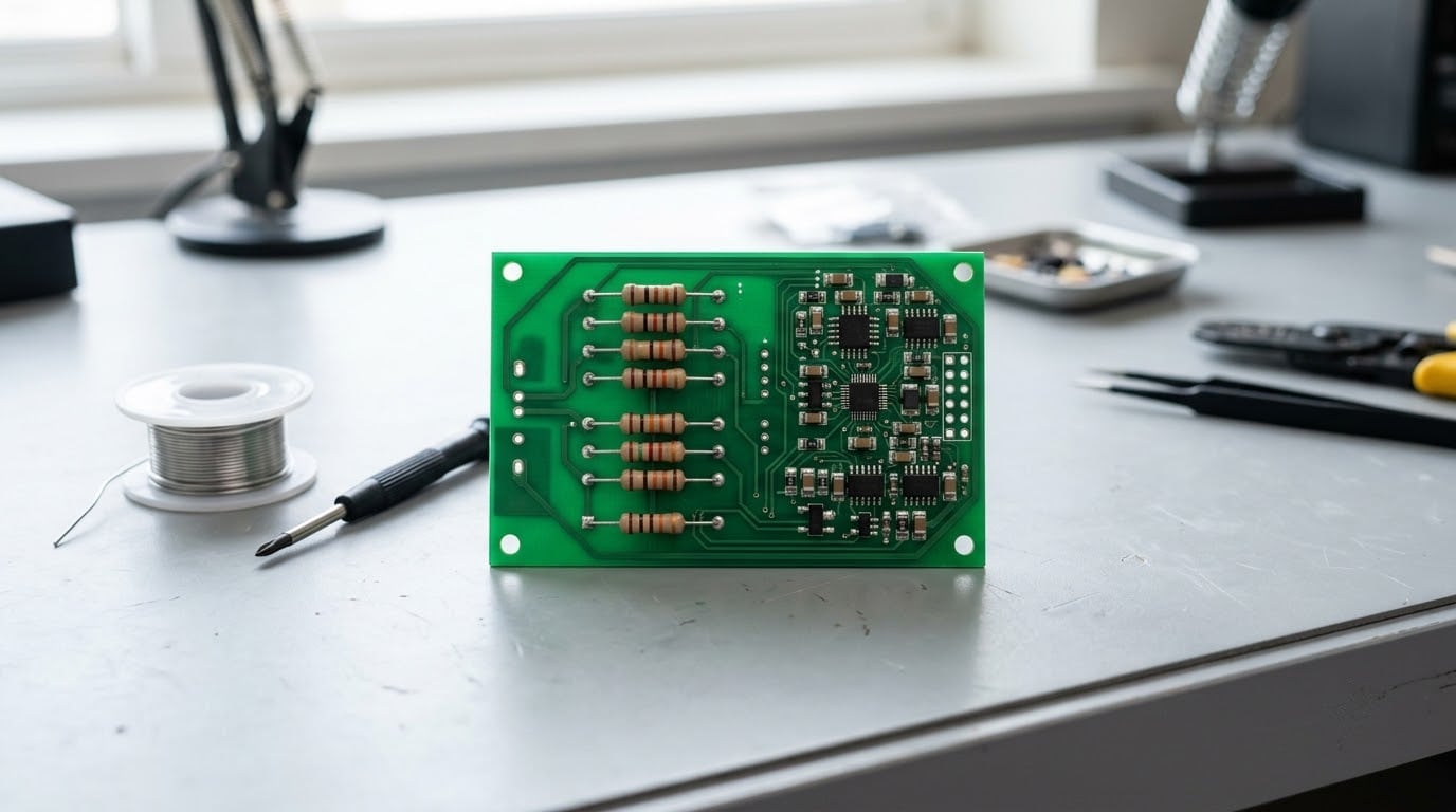
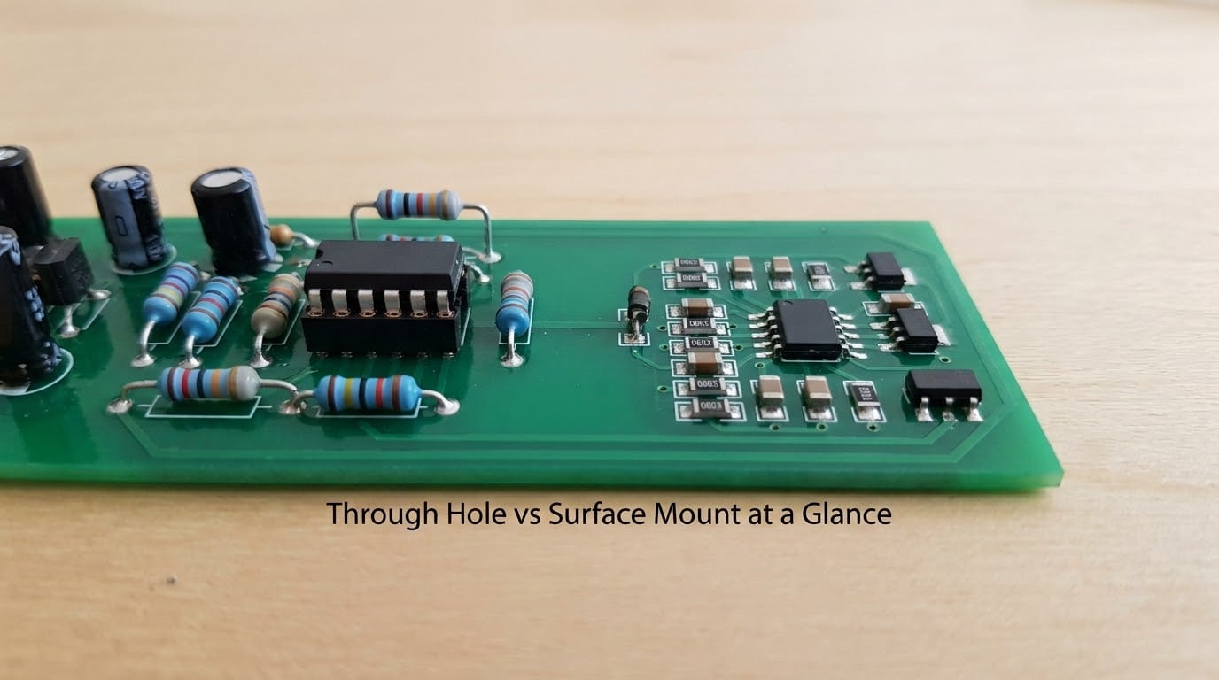
Through hole vs surface mount is not the close call it sounds like. Through hole puts component leads through drilled holes in the board and solders them on the far side, while surface mount attaches tiny parts onto copper pads on the top and reflows them in an oven. Through hole wins for your first prototype and for anything that gets knocked around; surface mount wins once you need small size, high density, or automated production.
I have built both kinds of boards, and the choice matters less than most guides make it sound like. Pick through hole when you are hand-assembling, repairing in the field, or mounting something heavy in a housing that vibrates. Pick surface mount when the board has to fit somewhere tight, carry a dense circuit, or get built more than once.
Here is how the two actually differ, criterion by criterion, followed by a straightforward recommendation for each kind of build.
Table of Contents
- Through Hole vs Surface Mount at a Glance
- What Is Through-Hole Mounting?
- What Is Surface-Mount Mounting?
- Assembly and Prototyping Differences
- Mechanical Strength and Vibration Resistance
- Thermal and Electrical Performance
- Cost, Space, and Production Scale
- Which Should You Choose?
- Frequently Asked Questions
- Conclusion
Through Hole vs Surface Mount at a Glance
| Criterion | Through hole (THT) | Surface mount (SMT) |
|---|---|---|
| Assembly method | Leads pass through drilled holes, soldered on the underside | Parts sit on copper pads, soldered to the top surface |
| Lead orientation | Axial or radial, long leads | Short leads, gull-wing, no lead, or solder balls |
| Mechanical strength | Very strong, joint anchors through full board thickness | Relies on pad area and solder fillet alone |
| Thermal performance | Long leads move heat to the far side, useful for power parts | Short paths to copper, better for dense heat sources |
| Board area | Large, holes limit routing density | Very small, roughly 60 to 90 percent less area per part |
| Prototyping | Easy, forgiving, easy to desolder and swap | Harder, 0402 and DFN parts need magnification or hot air |
| Repairability | Excellent, desolder with a pump or wick | Poor once assembled, joints hide under the part |
| Setup cost | Low, an iron is enough | Higher, stencil, paste, and reflow oven or hot plate |
| Per-part cost in volume | Higher at scale, more holes to drill | Lower at scale, placement machines are fast |
| Typical assembly method | Hand solder or wave soldering | Stencil, pick-and-place, reflow oven |
| Best suited to | Prototypes, repairs, vibration-prone gear | Compact products, automated production runs |
What Is Through-Hole Mounting?
Through-hole technology, or THT, means the component’s leads pass straight through a hole drilled in the printed circuit board and are soldered on the opposite side. The solder joint physically anchors the part through the entire thickness of the laminate, which is why it survives handling better than anything else you can put on a board.
Two lead styles show up. Axial parts such as resistors sit with their leads in a line along the board, so the body lies down between two holes. Radial parts such as electrolytic capacitors stand upright with both leads coming out of one side, which is denser and how most discrete parts ship today.
Why through hole stays popular
Through hole is still the default for prototypes because you can put a part in backwards, pull it out with solder wick, and put it back without damaging anything. Nothing about the joint is hidden, which makes it forgiving when your design changes three times in one weekend.
In production, through-hole boards usually get soldered by hand or run through a wave soldering machine, where the board rides on a conveyor through a wave of molten solder. Large parts, connectors, big capacitors, and anything that carries real current tend to be mounted this way because the joint can physically take the mechanical load of the wire being plugged and unplugged.
Plated through holes are the finished version: the barrel of the hole is copper-plated so it connects between layers in a multilayer board. Most boards mix both anyway, using plated holes for vias and through-hole pads for parts.
What Is Surface-Mount Mounting?
Surface mount technology, or SMT, attaches components directly to pads on the board surface with no hole at all. The part is called an SMD, and the joint exists only on the side you can see, formed from a small mound of solder connecting the lead or terminal to a flat copper pad.
How the reflow process works
Solder paste is printed through a stencil onto the pads, a pick-and-place machine sets each component into the paste, and the whole board goes through a reflow oven that ramps to about 245 degrees Celsius, melts the paste, and pulls the parts into position as the solder wets the pad. Every joint forms at once, which is why a machine can place thousands of parts an hour where a person places a few hundred.
Package sizes are named in imperial units, so 0402 measures roughly 1.0 by 0.5 millimeters. 0603 and 0805 resistors are comfortable for hand work with a good iron. 0402 is manageable, and 0201 or 01005 need magnification and steady hands. Larger packages include SOT-23 for small transistors, SOIC for analogue chips, QFP for processors with fine-pitch leads, and BGA packages where the connections hide underneath the chip entirely.
Because there is no hole to drill, you can pack parts on both sides of the board and route traces between them. That is where the space savings come from, and it is the single biggest reason surface mount won.
Assembly and Prototyping Differences
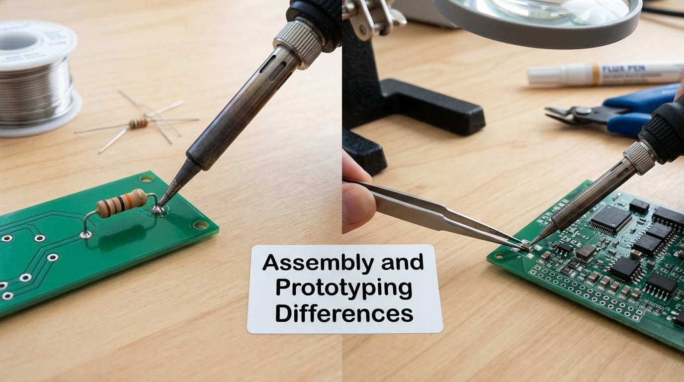
Hand soldering through hole needs a steady iron, a little flux, and about ten minutes per board. You push the leads through, clip them, and solder the underside. Mistakes are visible and correctable, and the board can go back in the iron as many times as you need.
Hand soldering surface mount depends entirely on package size. A 1206 or SOIC-8 part on generous pads is quite forgiving. A 0402 or a DFN with a thermal pad underneath is genuinely difficult without magnification, and it is the sort of job that makes beginners decide they hate surface mount. That is a tooling problem, not a soldering problem, and most of it disappears once you have a stereo microscope and a hot air rework station.
Iteration speed is the other difference. A through hole design change means drilling a new hole or moving a part, which takes minutes. A surface mount design change means a new paste stencil, a new placement program, and a reflow cycle, so changes get more expensive as the board fills up. This is exactly why experienced engineers prototype on through hole and move to surface mount only when the design has settled.
Hobbyist reflow is cheaper than people think
You do not need a factory oven to reflow a board at home. A toaster oven, a hot plate, or a cheap heat gun works fine with a low-temperature bismuth solder paste, which melts around 138 degrees Celsius instead of the usual 217. Electronics hobbyists on Reddit describe this setup as the point where hand soldering surface mount stopped feeling painful. A heat gun costs very little, and the paste itself is now inexpensive in small jars.
One myth worth killing: people assume surface mount means multilayer boards only. Nothing stops you doing a single-sided surface mount board, and plenty of designs are exactly that.
Mechanical Strength and Vibration Resistance
Through hole is the clear winner on mechanical strength, and the reason is geometric rather than mystical. The solder joint wraps a lead that runs the full thickness of the board, so pulling, twisting, or flexing the part loads copper, laminate, and solder together. A surface mount joint depends on the pad area and the fillet of solder around the terminal, so it has less material carrying the load.
That gap matters when something is installed in a place that moves. A sensor pod on a wave-following robot, a depth sounder mounted in a hull that slaps, a battery monitor bolted to a motor mount: these see continuous vibration and impact, and a through-hole connector will not creep out of its joint. The same reasoning applies to connectors and to any part where someone will eventually lean on it.
Surface mount handles vibration well when the board is rigid and the parts are small. A thin, flexing board with heavy surface-mount parts on it will crack the joints at the pad edges under repeated flexing, so the fix there is board stiffness or strain relief rather than a change of mounting technology.
The marine case in plain terms
Boat-mounted electronics deal with three things land electronics do not: constant low-level vibration, salt-laden humidity, and wide temperature swings. Through hole and conformal coating handle those better than a bare surface mount board. If your device will live in a wet locker or get splashed, sealing matters as much as the mounting choice, and no mounting method is waterproof on its own.
Thermal and Electrical Performance
Thermal results depend on what you are trying to move. A through-hole part with long leads has a decent path to the copper on the far side of the board, and spreading a large part over two holes turns the board itself into a heatsink. That is why big power diodes, regulators, and screw-mount fuses are often through hole.
Surface mount wins the opposite race. With essentially no lead length, less material is available to generate unwanted inductance or capacitance, so high-frequency and low-noise circuits get cleaner results. Shorter paths also cut signal delay, which is why RF front ends, switching regulators, and fast digital buses live on surface mount.
Heat is a fair criticism of surface mount when parts are small and packed. A tiny package cannot spread its own warmth, so a dense converter or amplifier needs copper pours, thermal vias, and deliberate spacing for heat to leave. Through hole at the same power level has more room to breathe.
Cost, Space, and Production Scale
For one board, through hole is cheaper in every way. No stencil, no paste, no oven, no placement machine, and no drilling cost on a single-layer design you cut yourself. If a contract assembler quotes you for a small run, the through-hole quote is usually higher per board because the setup is charged to you, but the total is still modest.
Past a few hundred boards, that flips. Placement machines place components far faster than any hand process, and a pick-and-place head running continuously gets through tens of thousands of parts a day. Wave soldering handles the through-hole parts on those same boards in one pass. Board area per part drops by roughly 60 to 90 percent with surface mount, which shrinks the raw board cost and often the enclosure.
Why the through hole vs surface mount choice is not always either-or
Press-fit mounting sits between the two. Solid pins push into plated through holes with friction fit and a cold solder joint forms over time, giving strong mechanical retention without a soldering iron. It suits high-volume mixed assembly where connectors need strength, but it demands tighter hole tolerances than a normal through-hole board, so it is a manufacturing decision rather than a hobby one.
Mixed-technology assembly is the practical answer for most product teams: surface mount for the signal and processing parts, through hole for connectors, large capacitors, and anything the user will touch. You get the density of surface mount without giving up the mechanical anchor where it counts.
Which Should You Choose?
Choose through hole for a first prototype, a classroom project, a breadboard-style build, or anything you expect to change twice. It is also the right answer for low-volume marine devices that will be serviced in the field, for any board that lives in a vibrating environment, and for designs using large parts, big connectors, or high-current devices.
Choose surface mount when size is the hard constraint, when the design needs parts per square centimeter that a drilled board cannot offer, when the circuit runs fast enough for lead inductance to matter, or when you are building the same design more than once and want automated assembly to carry the cost.
Ask three questions and the answer usually arrives on its own. Are you hand-assembling? If yes, through hole. Does the device see vibration or shock? If yes, through hole for connectors and heavy parts. Are you making more than a handful? If yes, surface mount, and consider a mixed board.
Frequently Asked Questions
Is through hole better than surface mount?
Neither is better in general. Through hole is easier to hand solder, repair, and swap, and it holds up better against vibration. Surface mount gives you smaller boards, higher density, cleaner high-frequency performance, and far cheaper assembly in volume. Most products use both on the same board.
Can you mix through-hole and surface-mount components?
Yes, and most real products do exactly that. A common pattern is surface mount for the logic and processing sections, with through hole for connectors, large capacitors, and anything the user plugs into. Assembly lines run reflow first, then wave or hand soldering for the through-hole parts on the same board.
Is surface mount harder to solder by hand?
It depends on package size. 1206 and 0805 resistors and SOIC packages are quite manageable with a good iron and flux. 0402 parts need magnification, and 0201 or 01005 need a microscope. Adding a hot air rework station makes most sizes routine and avoids lifting pads.
Which mounting method is better for vibration-prone equipment?
Through hole, for mechanical parts. Its joint anchors through the full board thickness, so it resists twisting and pull. Surface mount joints on a stiff board also survive vibration, but keep connectors, large capacitors, and anything carrying current as through hole, and add strain relief so the solder joint never takes the cable load.
Is through-hole mounting more expensive?
For a single board, through hole is usually cheaper because you need only an iron. In volume, surface mount is cheaper per unit because machines place parts far faster and each part uses much less board area. At small volumes a contract assembler may charge more for through hole because the setup is spread over few boards.
Which method is best for a first PCB prototype?
Through hole. You can insert parts in any order, see the joints, desolder mistakes, and redesign without reprinting a stencil or reworking a reflow profile. Experienced engineers commonly prototype on through hole and transfer the settled design to surface mount once the circuit works and volume justifies the setup.
Conclusion
Through hole versus surface mount comes down to one question: is this build one of a kind, or is it a product? For a prototype, a repair, or a device that will live in a vibrating or wet environment, start with through hole and move on. For compact hardware you intend to build more than once, design for surface mount and use through hole only where a connector or heavy part needs a mechanical anchor.
Either way, start today by laying out your parts on paper and checking which one leaves you room to fix your own mistakes.