Tuning a PID controller for a boat rudder comes down to one loop, tuned in a fixed order: get your sensors honest, set Ki and Kd to zero, raise Kp until the boat starts to weave, back it off until the weaving stops, then add derivative damping and a small amount of integral. Do it in sheltered water with a hand always on the helm.
Most people arrive here with a boat that already steers, badly. It weaves across the line in a lazy S, or it holds three degrees to port no matter what you ask it, or it snaps the rudder hard over for a two-degree course change. Those are three different faults and only one of them is solved by changing a gain.
This is how to tune a PID controller for a boat rudder in a way you can repeat and record, rather than guess at on a Saturday afternoon. It is written for makers and marine engineers who already have a heading source, a rudder actuator and a controller. Budget an afternoon at the dock and a couple of short sea trials. If your boat has no compass or no rudder position feedback yet, the first section below is where you stop and fix that first.
Table of Contents
- What You Need
- Step-by-Step
- Frequently Asked Questions
- Do I need a PID controller for a boat rudder?
- Should I tune P, I, or D first?
- Why does my autopilot oscillate after I increase gain?
- How much rudder travel is safe during PID tuning?
- Can I tune a boat autopilot in different software such as Ardupilot or Pixhawk?
- When is a PID problem actually a mechanical or sensor problem?
- Conclusion
What You Need
Gather this before you change a single number. Every item on the list exists because its absence produces a symptom that looks exactly like a tuning fault.
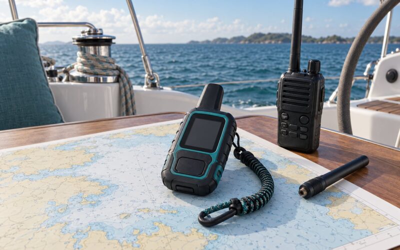
- A heading source. A calibrated magnetic compass with a deviation table, a GNSS receiver supplying COG heading, or an IMU. Magnetic compasses need a mounting offset and a deviation calibration against a known heading, otherwise the controller is chasing a sensor error, not a real course error.
- Rudder angle feedback. A potentiometer, encoder or linear transducer on the tiller or rudder post. This tells you whether the rudder moved where it was commanded, and it separates controller error from mechanical slop.
- A known-good actuator command range. Record your minimum, centre and maximum pulse widths or PWM values, and confirm the rudder reaches hard over at both ends without stalling against a stop.
- A heading log. Serial output to a laptop, an SD card, or a telemetry link. Log timestamp, commanded bearing, measured heading, error, controller output and, if you have it, yaw rate. You cannot tune what you cannot look at afterwards.
- A manual override that is proven, not assumed. A helm handwheel, tiller, or a mode switch you can reach without letting go. Test it before every trial.
- A crash-course alarm or heading watchdog. If the real heading strays too far from the commanded bearing, the controller should fall back to standby and hand control back rather than fight you.
- A low-risk test area. A sheltered bay or harbour mouth, flat water, light wind, and enough sea room to let the boat swing a full tack without putting anyone in danger.
- Tools and spares. Multimeter, a way to disable the actuator at the helm, spare batteries, and a person on board who is not busy with anything else.
Step-by-Step
1. Establish a Safe Test Baseline
Inspect the steering linkage first, because no controller can correct for a sloppy tiller. With the boat on a hard surface, work the helm from hard over to hard over slowly and watch for free play at the rudder itself. More than a few degrees of lost motion at the rudder is a mechanical problem, and it will look like oscillation once the autopilot is engaged.
Verify feedback next. Command ten degrees of rudder and confirm the rudder angle sensor reads ten degrees. If it reads something else, you have a scaling or offset problem. Verify the compass the same way: drive the boat through a slow circle and check that the reported heading matches a handheld compass at several points, then correct the mounting offset.
Select your water and your limits. Choose calm, sheltered conditions for the first pass, and decide in advance the rudder command and heading error at which you abort the trial. Confirm manual control before the autopilot is allowed to output anything at all. Set a conservative loop rate to begin with, typically somewhere around 0.2 to 1 Hz, so the loop reacts to the boat’s actual dynamics rather than to noise in the compass.
2. Measure the Rudder Response
Do one logging run at moderate speed with low gains before you tune anything. Ask for a 20-degree course change and record heading error, commanded rudder position, actual rudder travel and heading response over the following minute. This is the point where how to tune a PID controller for a boat rudder stops being opinion and becomes measurement.
That trace tells you which of three problems you have. Sluggish response, where the boat takes many seconds to begin turning and then swings past the target, points to a low loop rate, a weak actuator, or a boat that is simply too slow to have a rudder effect. Rapid oscillation, where the heading swings either side of the target several times before settling, points to loop gain or sensor noise. Steady drift, where the boat settles at a fixed offset and stays there, points to a persistent disturbance, a compass bias, or a missing integral term.
Write down the peak rudder command the boat used to make that turn. You will need that number later as your working output limit.
3. Tune Proportional Gain First
Set Ki and Kd to zero and tune Kp alone. That is the single most useful habit in this whole process, and experienced builders on the Arduino and cruising forums all say the same thing: bisect Kp before you add anything else.
Start with a modest Kp and a modest output limit, then double Kp after each short trial. Watch for the moment the boat first begins to weave at the new setting. Note the heading error amplitude, the rudder command at the peak, and the number of swings before it settles.
Too little Kp shows up as slow convergence, a large overshoot past the new course, and a rudder that never reaches a hard angle even when the heading error is big. Too much Kp shows up as weaving, hunting, and a hard snap when the setpoint changes. The usual rule is to back Kp off from the point where weaving first appears until the response is critically damped, which for most hulls leaves you in the range where the boat takes one gentle swing and stops.
Here is the whole loop in one table, so you know which knob moves which symptom:
| Term | What it changes on a boat | Too high looks like | Too low looks like |
|---|---|---|---|
| Kp (proportional) | How hard the rudder answers a heading error | Weaving, hunting, hard snap turns | Sluggish turn, big overshoot, weak disturbance rejection |
| Ki (integral) | Removal of a standing heading offset | Slow large oscillations, constant rudder activity, overshoot after a big course change | A permanent crab angle that never corrects |
| Kd (derivative) | Damping of yaw rate during a turn | Noisy twitchy steering, actuator wear, response to compass jitter | Every turn overshoots and rings before settling |
One note on the proportional term that catches people out. If you are simply scaling error linearly to pulse width with no integral and no derivative, that is a proportional controller, and it will always leave a standing offset. That is fine as a starting point, but do not mistake it for a tuned loop.
4. Tune Derivative Gain
Add Kd only once Kp is stable, and add it in small steps. Derivative acts on how fast the heading is changing, so it puts a brake on the swing at the end of a turn. On a boat that means the difference between one clean arc and an S-shaped path that gets worse on every leg.
Raise Kd until the overshoot after a 20-degree course change is gone and the boat settles without ringing. If you hear the actuator working harder while the boat sits straight, you have too much derivative, or you are taking derivative from raw compass data that is too noisy.
Two implementation details matter here. Take derivative from the measured heading rather than from the error, otherwise a step change in the commanded course produces a large spike in the output, known as derivative kick. And low-pass filter the heading signal before you differentiate it, or the compass noise gets amplified and the rudder starts chattering. A simple first-order filter with a time constant a few times your loop period is usually enough.
5. Add Integral Gain Carefully
Integral is what finally kills the standing offset, whether that offset comes from compass bias, a persistent wind or current angle, or a slightly miscalibrated mounting. It is also the term that most easily destabilises a loop that was previously calm.
Start Ki at a small fraction of what you used for Kp and increase it in steps. Watch for the classic symptom of too much integral: the boat holds its heading well, but after a large course change it swings well past the new course, returns slowly, and overshoots again. The longer you leave Ki in, the worse this gets, because the error is being stored while the rudder is already hard over.
Prevent that with anti-windup. Clamp the controller output to the real rudder limits and stop accumulating integral while the output is saturated. Reset or bleed the integral term when the commanded course changes by a large amount, since a long accumulated correction is meaningless once you have asked for something new. Keeping the loop linear and letting the actuator limits do the clamping is simpler and works better than special-case clamping rules for large errors.
6. Validate the Tuning in Changing Conditions
A loop tuned on one heading at one speed tells you very little. Run it at several headings around the compass, at several speeds, and in at least one condition with real wind or current pushing on the hull.
Test recovery as well as tracking. Deliberately create a disturbance, a course change, a moment of power interruption, or a large offset, and watch how the boat comes back. How long the recovery takes and how far it swings are better measures of the tuning than a smooth straight leg.
Test speed specifically. Hull speed is the point where rudder authority changes fastest, and below minimum steerage speed the boat often will not turn at all no matter what the controller commands. If gains that are calm at cruise make the boat sluggish at low speed, or weave badly when it picks up way, that is a gain-scheduling problem, not a tuning error. The same applies to asymmetry: prop walk, keel load and heel often make the port and starboard turns different enough that one side needs a slightly scaled Kp.
Do not draw conclusions from a single manoeuvre. One long straight leg tells you almost nothing about transient behaviour.
7. Save and Fine-Tune the Final Settings
Write down the final gains along with everything that produced them: the sensor and compass calibration, the rudder limits, the loop rate, the speed, the sea state, and the symptoms you were fixing. A bare number like Kp 4.0 means nothing six months later.
Log your trials properly and you can re-tune without re-sailing. Replay a recorded heading trace through a model of your loop on a laptop, change one gain, and compare the result. That single habit separates people who tune a boat in a season from people who tune it in a weekend.
Treat any final value as a starting point for the next condition rather than a universal correct answer. A boat that behaves well on a flat morning may need less Kp and a little more Ki for a following sea. Small adjustments, recorded each time, beat a large re-tune that undoes something that was working.
Common Mistakes
Almost every failed boat autopilot run comes down to one of these. The fix is nearly always cheaper than more gain hunting.
| Observed behaviour | Likely cause | Specific adjustment |
|---|---|---|
| Boat weaves or zig-zags along the track | Kp too high, or the loop only has a heading error term and no cross-track term | Halve Kp and retest. If the track error is still large, add a cross-track error term rather than chasing it with Kp |
| Steady offset that never corrects | Ki too low, compass bias, or uncalibrated deviation | Add a small amount of Ki, and re-run compass deviation calibration before trusting the gains |
| Hard snap and overshoot on small course changes | Derivative kick, or Kp too high for the loop rate | Use derivative on measurement, filter the heading, and reduce Kp |
| Rudder buzzing or clattering while sitting on heading | Compass noise amplified by D, or deadband too small | Lower the derivative filter cutoff and set a small deadband in the controller |
| Oscillation that only appears in current or wind | Constant disturbance fighting a loop with no integral | Add a small Ki with anti-windup clamping, and check the loop is not saturated |
| Error looks right but the boat turns away from the target | Sign convention on the error term | Compute error as heading minus bearing, wrapped to plus or minus 180 degrees, with a setpoint of zero |
Two more worth naming. Change all three gains at once and you learn nothing, because you cannot attribute the result. And never skip the manual override check: if the helm does not work with the autopilot switched off, it is not an override, it is a hope.
Frequently Asked Questions
Do I need a PID controller for a boat rudder?
You need closed-loop control of some kind. A proportional-only controller will hold a heading, but it always leaves a standing offset, because nothing corrects for a persistent wind or current angle. Adding integral removes that offset and adding derivative damps the swing at the end of each turn. Whether you implement that as a classic PID, a cascaded heading and rudder-angle pair, or a modern nonlinear controller matters less than having feedback, bounded output and a working manual override.
Should I tune P, I, or D first?
Tune P first, then D, then I. Set Ki and Kd to zero, raise Kp in steps until the boat begins to weave, then back it off until the weaving stops. Add Kd until overshoot after a course change disappears, and only then add a small amount of Ki to remove the standing offset. Tuning all three at once makes the result impossible to interpret, because you cannot tell which term produced the change you saw.
Why does my autopilot oscillate after I increase gain?
Oscillation after a gain increase usually means you have passed the point where the loop can settle. Check three things before touching the gains again. Make sure compass noise is not being amplified, that any derivative filter is set, and that mechanical free play at the tiller is not being amplified into a hunting loop. Then bisect the gain you just changed and retest. If the weaving persists at half the value, the fault is mechanical or in the error term, not in the gain.
How much rudder travel is safe during PID tuning?
Use the least rudder the boat actually needs to make a normal 20 to 30 degree course change, plus a margin. Establish that number from a logged trial before you tune, then set the controller output limit to it. A tight output limit is your best protection against a snap turn: the actuator cannot do anything the hardware and the hull cannot absorb. Below minimum steerage speed no limit will help, because the rudder simply has no effect in the water.
Can I tune a boat autopilot in different software such as Ardupilot or Pixhawk?
Yes, the physical method is identical, but the terms are named differently in each stack. In general-purpose autopilot software the outer loop computes a desired turn rate and a heading controller drives the rudder, so you will be adjusting rate and heading gains rather than a single classic PID triple. The order of work does not change: calibrate sensors, set limits, tune the proportional response first, add damping, then add the slow offset correction. Check your own version documentation for the exact parameter names.
When is a PID problem actually a mechanical or sensor problem?
It is mechanical or sensory when the symptom follows the hardware rather than the conditions. Rudder buzzing at rest, a boat that will not hold a heading at the same angle twice, or an error signal that jumps when nothing has changed on the water all point at backlash, a loose linkage, an uncalibrated compass or a failing rudder angle sensor. Set the gains to zero and confirm the sensors report sensible, repeatable values. If the readings are wrong with the loop disabled, no gain setting will ever fix it.
Conclusion
If you take one thing away from how to tune a PID controller for a boat rudder, make it this: verify the rudder feedback, calibrate the compass, and prove the manual override, all in sheltered water with the controller disabled. Then zero Ki and Kd, raise Kp until the boat weaves, and back it off until it settles cleanly.
Only after that should you add derivative damping and a small amount of integral, logging every trial so the next condition is easier than this one. Replaying those logs offline is how you avoid re-sailing for every single gain change.