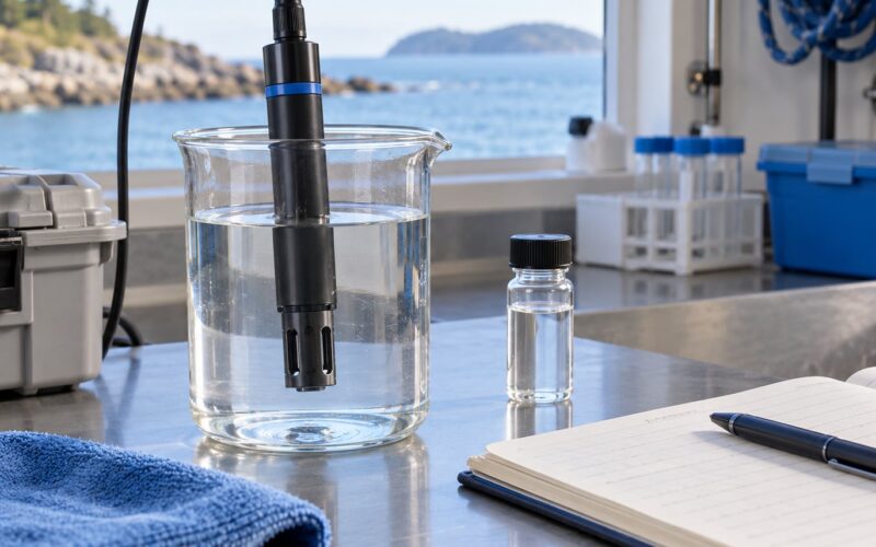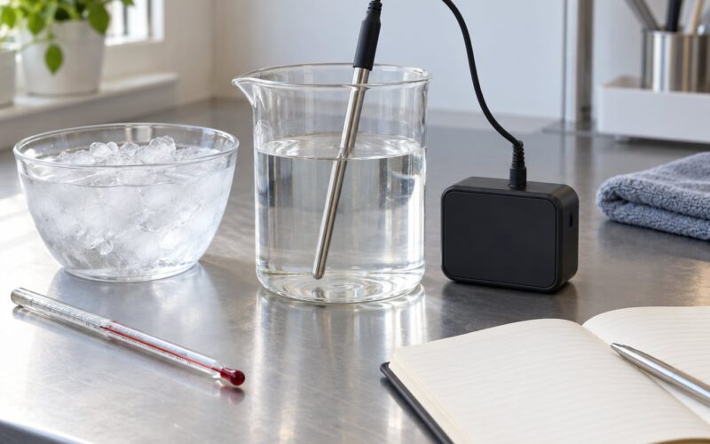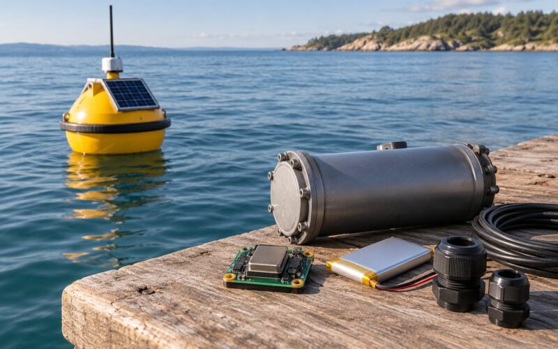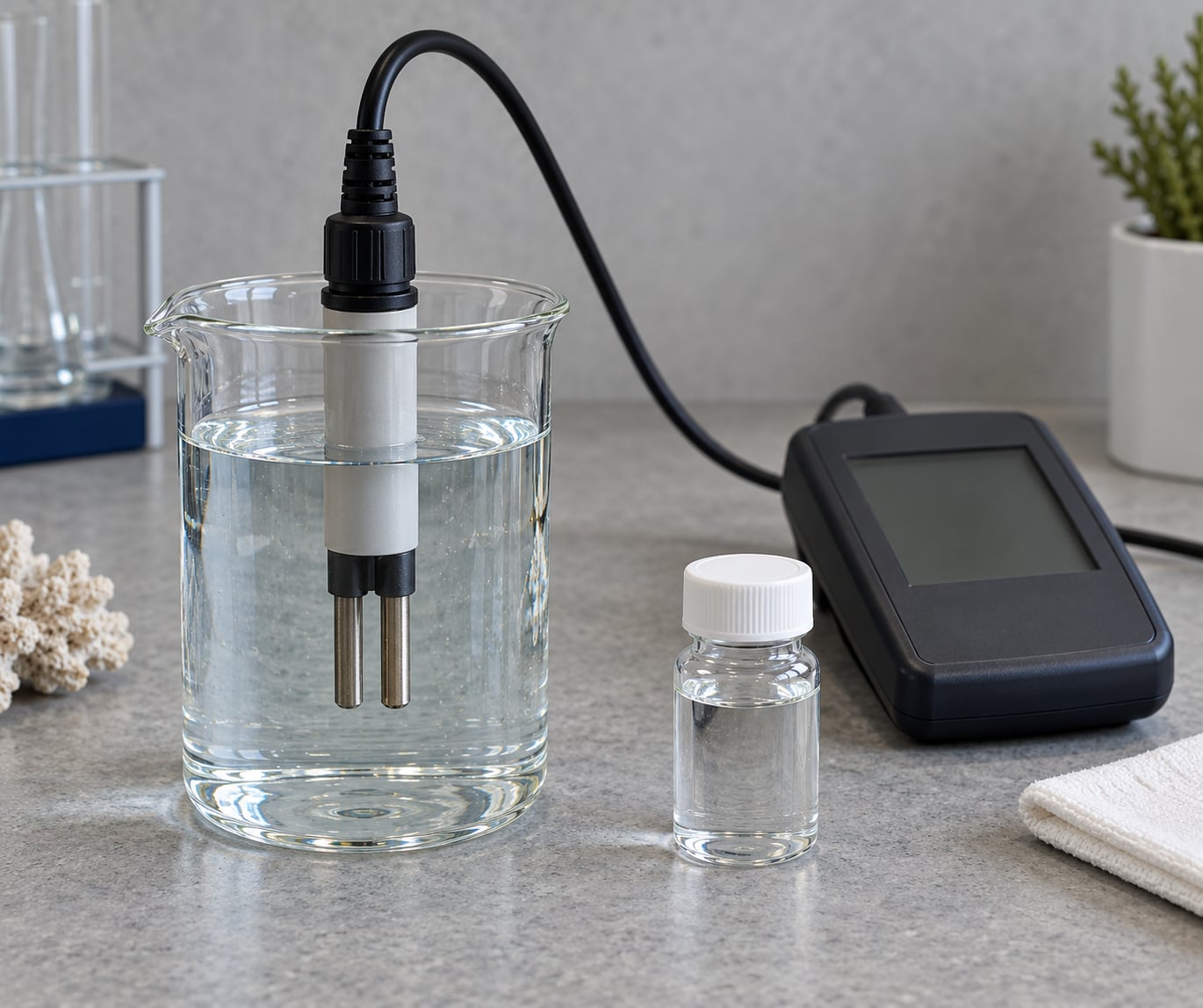
A conductivity sensor never touches salt directly. It passes a small alternating current through the water between two or four electrodes, measures how easily that current flows, and multiplies the result by the cell constant to produce a conductivity value in mS/cm or µS/cm. Salinity only appears at the end, as a calibrated conversion of that number at a known temperature.
For anyone putting sensors on a sailing robot, an ocean drone or a moored buoy, that distinction matters. The instrument gives you a clean electrical measurement. Everything between that number and a salinity value is where the accuracy is won or lost.
This guide walks the chain in order: what the cell actually measures, why temperature has to come along for the ride, how the conversion is done, and how to catch the field problems that quietly ruin a dataset.
Table of Contents
- How Conductivity Sensors Measure Salinity
- What the Electrical Reading Represents
- Why Temperature Compensation Matters
- How Readings Become Salinity
- Which Conductivity Sensor Type Should You Use?
- How Accurate Are Salinity Measurements?
- How to Use Conductivity Sensors in an Ocean Robot
- Frequently Asked Questions
- Is conductivity the same as salinity?
- Why do conductivity sensors need temperature readings?
- Can the same calibration convert freshwater and seawater readings?
- How often should an ocean robot conductivity sensor be calibrated?
- What causes a conductivity reading to be inaccurate in the field?
- Which sensor type works best for a low-power sailing robot?
- Start With a Validated Measurement Chain
How Conductivity Sensors Measure Salinity
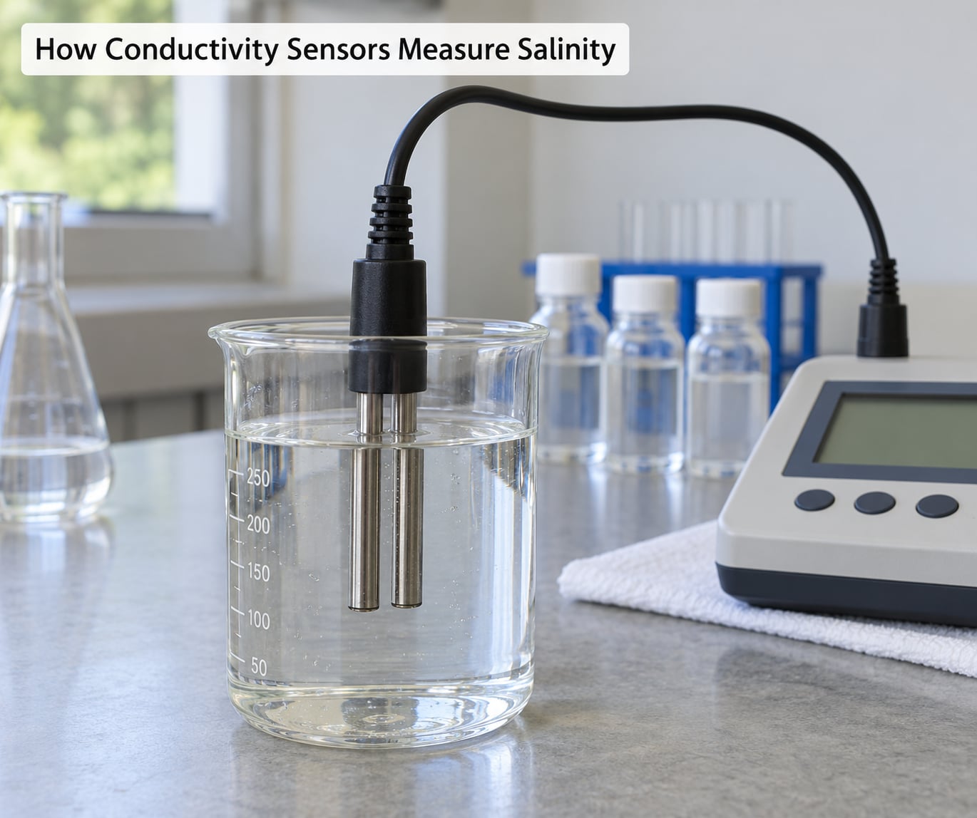
Here is the short version: a sensor excites the water with a small AC voltage, measures the current that comes back, works out the conductance of the water between the electrodes, converts that to conductivity using the cell constant, corrects the result to a reference temperature, and then runs a standard algorithm to turn the corrected conductivity into a salinity number. Six steps, and the first five are electrical.
The chain in full:
- Excite the water. The instrument applies a low AC voltage, usually at 50/60 Hz or a few kHz, across the electrode pair.
- Let current flow. Dissolved ions move between the electrodes. Sodium carries positive charge, chloride carries negative charge, and the water itself carries a little too.
- Measure voltage and current. Most instruments either apply a known current and measure the resulting voltage, or apply a known voltage and measure the current.
- Compute conductance. Ohm’s law gives you the resistance of the water between the electrodes, and its reciprocal, the conductance, in siemens.
- Apply the cell constant. Conductance multiplied by K, the ratio of electrode spacing to electrode area, gives conductivity in µS/cm or mS/cm.
- Compensate and convert. A built-in temperature sensor corrects the reading to a reference temperature, then a published algorithm maps conductivity to practical salinity.
Steps one through five are measurement. Step six is interpretation, and it is the only place where the word salinity belongs.
What the Electrical Reading Represents
The reading at the electrodes is conductance, not conductivity, and the distinction is where a lot of confusion starts. Conductance depends on the whole cell. Cut the water volume in half between the same two electrodes and the conductance doubles even though the salinity did not change. Conductivity is the property of the water itself, and the cell constant is what removes the geometry from the number.
Cell constant K is simply electrode spacing divided by electrode area, expressed in cm⁻¹. A cell with electrodes 1 cm apart and 1 cm² in surface area has K = 1 cm⁻¹. A longer, narrower cell has a higher K and therefore a lower conductance for the same water, which is how one instrument design covers a range from drinking water to full seawater without redesigning the electronics.
AC excitation is the normal choice, and the reason is chemical. A DC voltage drives electrolysis at the electrodes, plating one and dissolving the other, and it also polarises the electrode surfaces, adding a large and temperature-dependent resistance that has nothing to do with the water. Reversing the current several times a second averages that polarisation out of the measurement.
Conductivity is normally reported in microsiemens per centimeter (µS/cm) for fresh water and millisiemens per centimeter (mS/cm) for salt water. Yes, sodium chloride carries high conductivity. Dissolving it splits the crystal into mobile Na⁺ and Cl⁻ ions, and that conductivity is why you get a measurable signal at all. Which matters here: the sensor responds to any ion in the water, not salt specifically.
That is the core limitation. A cell full of dissolved acid, fertiliser runoff or sewage sludge will conduct just as well as seawater. Conductivity tells you the total load of charge carriers. Salinity is a specific claim about salt, and only the conversion step adds it.
Why Temperature Compensation Matters
Water conducts about 2% more current for every degree Celsius it warms, while the dissolved salts stay exactly where they were. An uncompensated sensor watching a buoy through a summer day can report a salinity swing of several units that is nothing but the water getting warmer.
That is why nearly every modern cell carries its own temperature sensor. The instrument takes the raw reading, then rescales it to a reference temperature, almost always 25 °C, using a coefficient expressed in % per °C. The result is specific conductance: the conductivity the sample would have shown at the reference temperature. The real water is not at 25 °C, but the number is now comparable with every other reading you will ever take.
Seawater’s coefficient sits around 1.8 to 2.1 %/°C, and freshwater’s runs closer to 2.0 %/°C. Most instruments ship with a 2.0 %/°C default, which is why the compiler of a data logger is a real decision rather than a checkbox. Set it for the water the robot actually swims in, and record the setting in your metadata. The difference between a 1.8 and a 2.0 coefficient over a 15 °C swing is not trivial at the third decimal place.
Two things to hold onto. A compensated reading is a derived number, not a measurement, so keep the raw value and temperature alongside it. And compensation fixes temperature, not composition. It cannot tell a warm sample of seawater from a warm sample that happens to conduct the same amount for a different reason.
How Readings Become Salinity
Salinity is reported as practical salinity, a unitless number from the Practical Salinity Scale 1978 (PSS-78), which was built for oceanographic work on the conductivity relationship. A reading of 35 is standard open-ocean water, roughly 35 grams of dissolved salts per kilogram of seawater, and that definition is exactly the same relationship a modern cell reproduces. The 1978 scale was anchored to KCl calibration standards, which is why traceable KCl solutions still calibrate oceanographic cells.
The conversion needs four things in hand: the temperature-compensated conductivity, the in-situ temperature, the cell’s range, and an algorithm that suits the water type.
Fresh water and seawater are not the same conversion. Fresh water below roughly 0.5 practical salinity is dominated by calcium carbonate and other non-salt ions, so the conductivity-to-salinity curve flattens and becomes noisy. Seawater holds its major ions in an almost fixed ratio, which is the only reason a single curve works across the open ocean at all. Brackish and estuarine water sits in between, where the ratio shifts with river discharge and the conversion is genuinely uncertain. If your robot works an estuary, treat conductivity-derived salinity as a trend rather than a number to defend.
TEOS-10 goes further, converting practical salinity into absolute salinity in g/kg using a density model, which corrects for the compression of seawater at depth. It matters for profiling work and for anyone comparing readings across pressure. For surface deployments, PSS-78 is enough, and adding a pressure correction on top of a shallow sensor is a common way to introduce error rather than remove it.
Reference values to sanity-check a reading against, at 25 °C:
| Water type | Conductivity | Practical salinity | Approx. dissolved salt |
|---|---|---|---|
| Deionized water | 0.5 to 5 µS/cm | 0 | near zero |
| Fresh water, typical | 200 to 1000 µS/cm | 0 to 0.5 | 100 to 500 ppm |
| Brackish, estuary | 0.5 to 5 mS/cm | 0.5 to 20 | 0.5 to 12 g/kg |
| Open ocean, average | about 35 mS/cm | about 35 | about 35 g/kg |
| Red Sea, hypersaline | over 55 mS/cm | over 40 | over 40 g/kg |
One warning that catches almost everyone: a cell specified for 0 to 500 µS/cm cannot resolve seawater. Its full-scale output saturates somewhere around 2 mS/cm, so a 35 mS/cm sample reads as the same number as a slightly saltier one. Match the cell range to the water, not the other way round.
Which Conductivity Sensor Type Should You Use?
Three designs cover almost all marine work, and the choice turns on how long the sensor sits in the water, what it costs to power, and how dirty the water gets.
| Type | Principle | Maintenance | Fouling risk | Power | Suits |
|---|---|---|---|---|---|
| Two-electrode | AC between two electrodes, cell constant applied to the conductance | Highest, electrodes need frequent cleaning | High, small exposed surface area | Low | Short deployments, tanks, bench work, clear water |
| Four-electrode | Two electrodes drive current, two sense voltage, so geometry stops drifting the result | Lower, sensing pair stays out of the current path | Medium | Medium | Moored buoys, coastal stations, longer deployments |
| Inductive (toroidal) | No electrodes touching the water; the field drives current around a sealed toroid and senses it through the housing | Very low, nothing metal in the water | Lowest, coating the coil only shifts calibration slightly | Medium to high | Dirty, silty, biofouling-prone water and estuary work |
Two-electrode cells are the cheap, simple choice and the right one for a tank or a weekend on the water. They are also the cell most likely to need scrubbing, because the electrodes are small exposed discs that collect biofilm in a matter of days.
Four-electrode cells separate the current path from the voltage measurement, so fouling on the sensing pair does not shift the reading the way it does on a two-electrode design. The inductive probe is the sturdiest of the three because there is no electrode in the water at all, at the cost of more electronics, more power, and a real price jump.
On a low-power autonomous platform, the decision usually comes down to the two-electrode and four-electrode options. Induction wins on fouling, not on energy, and a sailing robot has an energy budget measured in watt-hours per day.
How Accurate Are Salinity Measurements?
Good conductivity cells are accurate to well under one percent of reading in a bench bath. Field salinity figures are looser than that, because calibration, temperature, pressure and fouling each add their own error on top.
Calibration is the foundation. Standard practice uses traceable KCl solutions: 1413 µS/cm at 25 °C for fresh water work, and a higher standard around 50 mS/cm for seawater, since a 12.8 mS/cm solution is a reasonable check for a mid-range cell but calibrates a seawater cell at only a fraction of full scale. A two-point calibration, one standard plus a zero, holds better across the range than a single-point adjust. Rinse the cell thoroughly between solutions, agitate gently to clear bubbles from the electrode faces, and wait for the reading to settle before you accept the value.
Where the remaining error comes from:
| Error source | Typical size | How to reduce it |
|---|---|---|
| Calibration | 1 to 2 % of reading | Traceable KCl standard, two-point, fresh cell |
| Temperature coefficient mismatch | 1 to 2 % over a wide swing | Set the coefficient for the actual water, log it |
| Ion species difference | 1 to 3 % between seawater and a KCl standard | Calibrate in a seawater-matched solution where it matters |
| Pressure at depth | About 0.06 practical salinity per 200 dBar | Ignore below roughly 20 m, correct with TEOS-10 above it |
| Biofouling on the cell | 2 to 10 %, growing with time | Wipers, coatings, regular recovery and cleaning |
| Trapped air bubbles | Large and erratic, often 5 to 20 % | Tilt the cell, tap it, flush the flow path |
| Progressive drift | Slow, over weeks to months | Re-calibrate against a known sample after each deployment |
Bubbles deserve their own warning because they are the most common self-inflicted error. A bubble sitting on an electrode face is an insulator, and the reading climbs in ways that look like a real salinity event. Tilt the cell, tap the housing, and watch whether the number settles back down.
Before a deployment, put the cell in a solution you trust and confirm the number matches. After recovery, do it again. If the two disagree by more than the accuracy you claimed, you have fouling or drift, and the deployment tells you about the water, not the sensor.
How to Use Conductivity Sensors in an Ocean Robot
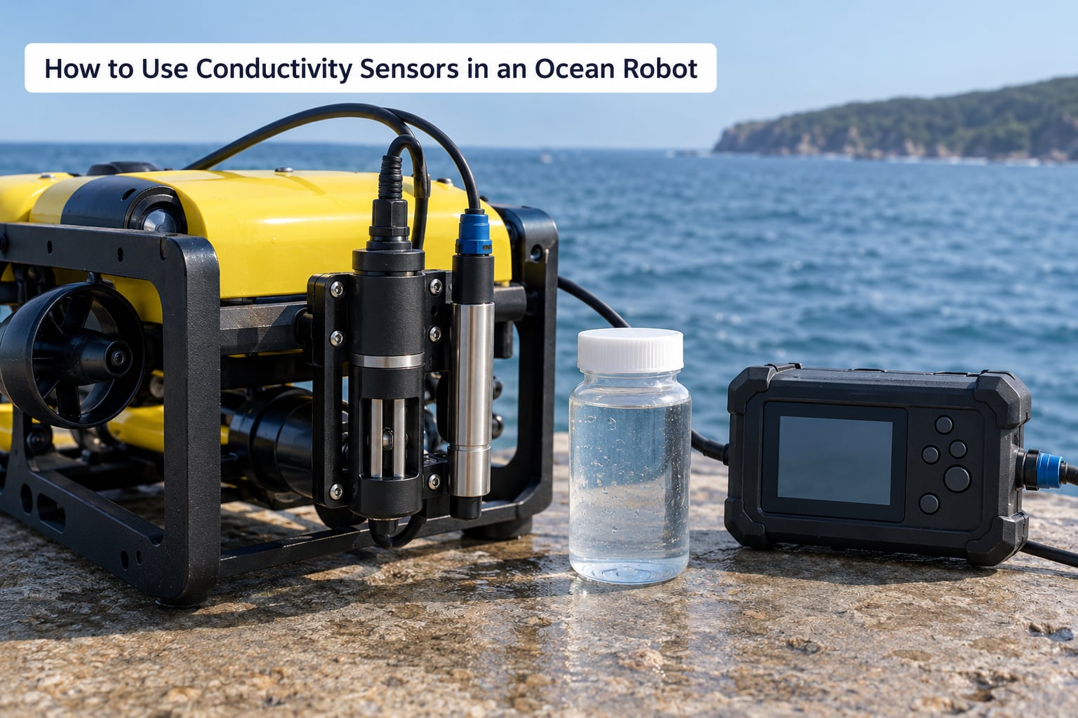
Mount the cell where water actually moves past it. A cell buried in a stagnant pocket of the hull reads the temperature of that pocket, not the sea, and stagnant flow is also where biofilm settles in first. A flow-through cell fed by a small pump gives a steadier reading and rinses the electrodes, at the cost of the pump’s power draw.
Mount it where the cable cannot chafe and where a foul growth would be visible on a recovered unit. Protective wipers and antifouling coatings help, but check the coating’s effect on the reading rather than assuming it is neutral.
Wire the cell and the temperature probe to the same logger channel group, and log them as one record. Conductivity without temperature is a number you cannot use later, and separating them on the timeline is a data-processing mess you do not need to inherit.
Write down the calibration detail before you sail: the standard used, its value, the temperature it was poured at, the coefficient setting, the cell constant, and the date. That sheet is the only thing that makes a two-year dataset auditable.
Set up automatic flags in the logger. A change larger than a few units per minute is almost always a sensor artefact, not an ocean event. No reading at all for a period is a disconnected probe or a short cable. Values sitting exactly on full scale mean the cell range is wrong for the water. Flag those, keep them in the record, and exclude them from analysis later rather than deleting them quietly.
On power, the cell itself is cheap. The expensive part is whatever you add to keep it clean, so a wiper motor or a pump will dominate the budget. Budget for the antifouling decision early, because retrofitting a flow-through system after the hull is closed is a much worse afternoon.
And reduce fouling without harming the cell. Never scrape the electrodes with metal, and never use anything abrasive on a four-electrode sensing pair. A soft brush, a rinse, and a dilute household-acid soak for scale are enough. Anything stronger risks the coating the manufacturer applied for a reason.
Frequently Asked Questions
Is conductivity the same as salinity?
No. Conductivity measures how easily current moves through water, which any dissolved ion will support. Salinity claims a specific amount of salt. The two track each other closely only in seawater, where the ratio between major ions stays nearly constant. In fresh and brackish water, calcium carbonate, nutrients and organics all contribute to conductivity without being salt, so the conversion loses accuracy.
Why do conductivity sensors need temperature readings?
Water conducts roughly 2% more current for each degree Celsius it warms, even when the dissolved salt is unchanged. An uncompensated sensor would report that warming as a salinity change. A built-in temperature probe lets the instrument rescale every reading to a reference temperature, usually 25 C, so values stay comparable across seasons, depths and different instruments.
Can the same calibration convert freshwater and seawater readings?
Not reliably. A KCl standard suits fresh water work, where 1413 uS/cm is the common reference. Seawater needs a higher standard, often around 50 mS/cm, because a KCl solution does not reproduce seawater’s ion makeup. The species difference alone introduces a few percent error, and a fresh water calibration applied to open ocean data will read high.
How often should an ocean robot conductivity sensor be calibrated?
Before every deployment and again after recovery, against a traceable standard. Between deployments, a check against a solution of known conductivity is enough to catch fouling. Long-term installations can run monthly checks. Drift is progressive, so a cell that was accurate at launch is not automatically accurate three months later, and a full recalibration is cheap compared with a corrupted dataset.
What causes a conductivity reading to be inaccurate in the field?
Bubbles trapped on the electrode faces are the most common cause and produce large erratic shifts; tilt and tap the cell to clear them. Biofouling adds two to ten percent over days to weeks. A cell range matched to fresh water saturates in seawater, drift accumulates slowly, and a mismatched temperature coefficient misreports every reading. Cable insulation damage adds a parallel resistance path that looks like conductivity.
Which sensor type works best for a low-power sailing robot?
A four-electrode cell is the usual answer. Its sensing pair stays out of the current path, so early biofilm distorts it less than on a two-electrode cell, and it needs no pump. An inductive probe fouls least but draws more power and costs more. If energy is very tight, a two-electrode cell with manual cleaning between sails is a reasonable compromise.
Start With a Validated Measurement Chain
Start with a measurement you can defend rather than a number that looks right. Calibrate the cell against a traceable standard, log temperature alongside every conductivity value, confirm the conversion algorithm suits the water the robot will actually see, and check the result in a known solution before you trust it for navigation or environmental claims. Everything after that is deployment detail.