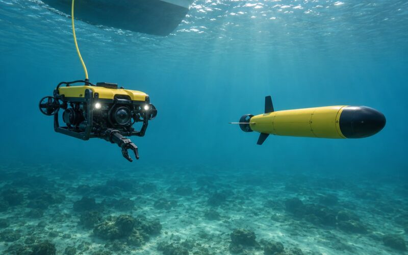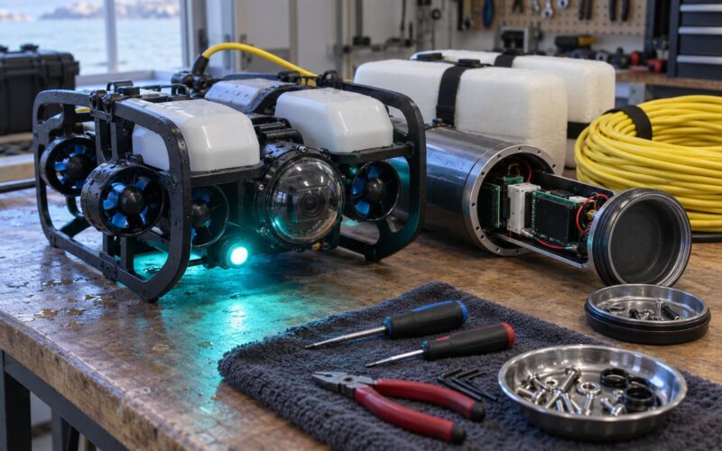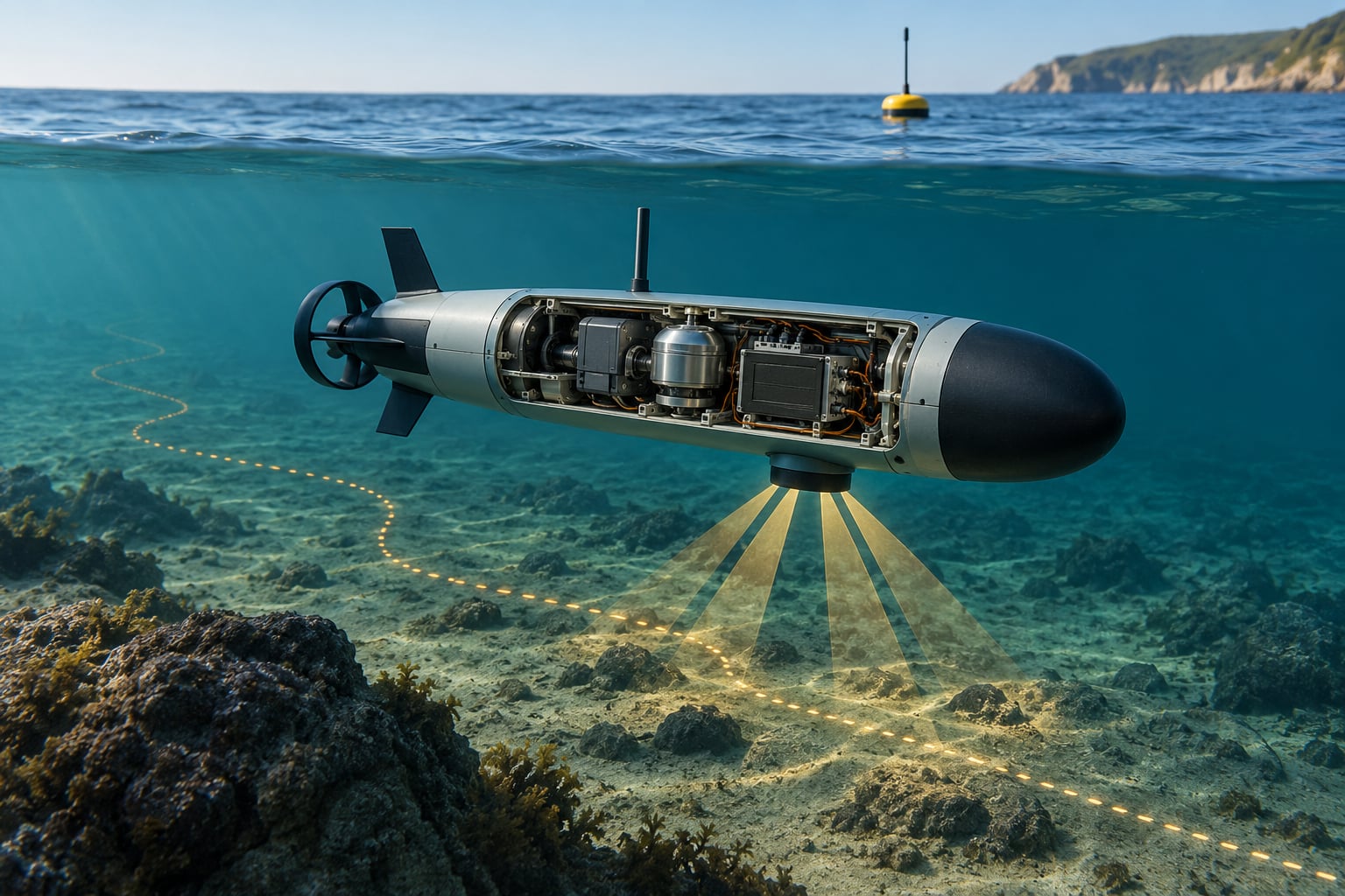
How dead reckoning works underwater is simpler than it sounds and harder to do well than most people expect. The vehicle takes its last known position, adds measured velocity multiplied by elapsed time, repeats that step dozens of times a second, and slowly builds an estimate of where it is right now. No satellite signal, no landmark, no external reference — just motion data and arithmetic.
GNSS signals are effectively dead the moment a vehicle submerges, so this self-contained method is the one navigation approach that always has something to say. The weakness is equally predictable: every small error gets integrated into every future estimate.
I have watched small ROV pilots discover this the hard way, flying a fixed heading and returning forty minutes later to find they ended up somewhere else entirely. This guide walks through the mechanics, the sensors, the error growth and the fixes that pull an estimate back to true.
Table of Contents
- What Is Underwater Dead Reckoning?
- Why Is It Called Dead Reckoning?
- How Dead Reckoning Works Underwater Step by Step
- What Sensors Measure Position and Motion?
- How Do Inertial Sensors Estimate Underwater Movement?
- How Accurate Is Dead Reckoning Underwater?
- What Happens When the DVL Loses Bottom Lock?
- How Do You Correct an Underwater Position Estimate?
- What Is the Difference Between Dead Reckoning and GPS Navigation?
- How Can Marine Robots Make Dead Reckoning More Reliable?
- Frequently Asked Questions
- Getting Started With Underwater Dead Reckoning
What Is Underwater Dead Reckoning?
Underwater dead reckoning is position estimation by integration. Start from a known fix, measure how fast the vehicle is moving and in what direction, add velocity times time to the previous position, and do it again on the next timestep. Nothing external is required once the run starts.
That single constraint explains everything about subsea navigation practice. A vessel on the surface can take a fresh satellite fix every second and throw away its whole error history each time. A submerged vehicle cannot, so the estimate is built from motion sensors alone and every fix becomes precious.
Why Is It Called Dead Reckoning?
The word “dead” has nothing to do with danger. The Oxford English Dictionary records the term from 1613, where “dead” meant exact or precise, as in a dead reckoning being a strictly exact one. The popular idea that it comes from “deduced reckoning” is a folk etymology repeated so widely that it now sounds authoritative.
Sailors on the YBW forum argue about this one regularly, and the honest summary is that the derivation is not fully settled. What is not in dispute is the strict technical meaning, which comes from the Admiralty Manual of Navigation and Bowditch: position derived from true course steered and speed through the water, and from no other factors.
Everything else — tide, set, current, leeway — pushes the answer into estimated position territory, which is a separate and slightly looser concept.
How Dead Reckoning Works Underwater Step by Step
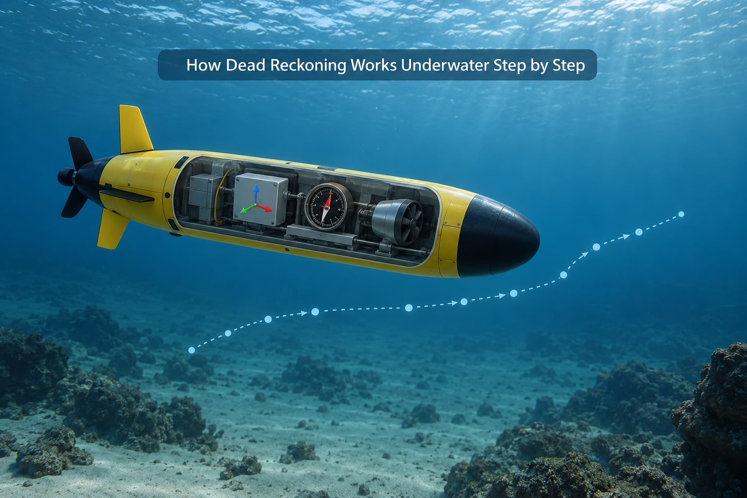
1. Acquire an initial position fix
The vehicle must start somewhere known. On a surface vessel or an AUV that launches and dives, this comes from a GPS fix at the surface. A tethered ROV normally inherits its start position from the tether entry point on the umbilical and the boat’s own GPS position.
2. Seed the position and orientation estimate
That fix, plus the current depth and a heading reading, is loaded into the navigation computer as the starting state. From here on, nothing external is needed to keep the estimate moving.
3. Measure velocity and motion continuously
A Doppler velocity log supplies body-frame velocity relative to the seabed when it has bottom lock. An IMU supplies angular rate and specific force. A pressure sensor supplies depth. These three streams feed the estimator at a rate of 50 to 200 Hz typically.
4. Rotate body-frame velocity into the navigation frame
This is what dead reckoning works underwater in a nutshell: raw velocity is measured relative to wherever the vehicle happens to be pointing, so it has to be rotated into north-east-down coordinates using the current orientation before it means anything as a displacement.
5. Integrate and propagate to the next timestep
The rotated velocity is multiplied by the timestep and added to the position. Orientation is integrated from gyro rates. The whole state — position, velocity, orientation, and the biases being estimated — is stepped forward again. This is the strapdown integration loop, and it never closes on its own.
6. Apply corrections and re-anchor the estimate
When an acoustic range arrives, or the vehicle surfaces for GPS, the estimator pulls its solution toward that measurement. Between corrections, the estimate is entirely self-built, and its uncertainty grows monotonically.
That loop is why dead reckoning is described as appropriate for fixing position during navigation only as the bridge between real fixes, never as a replacement for them.
What Sensors Measure Position and Motion?
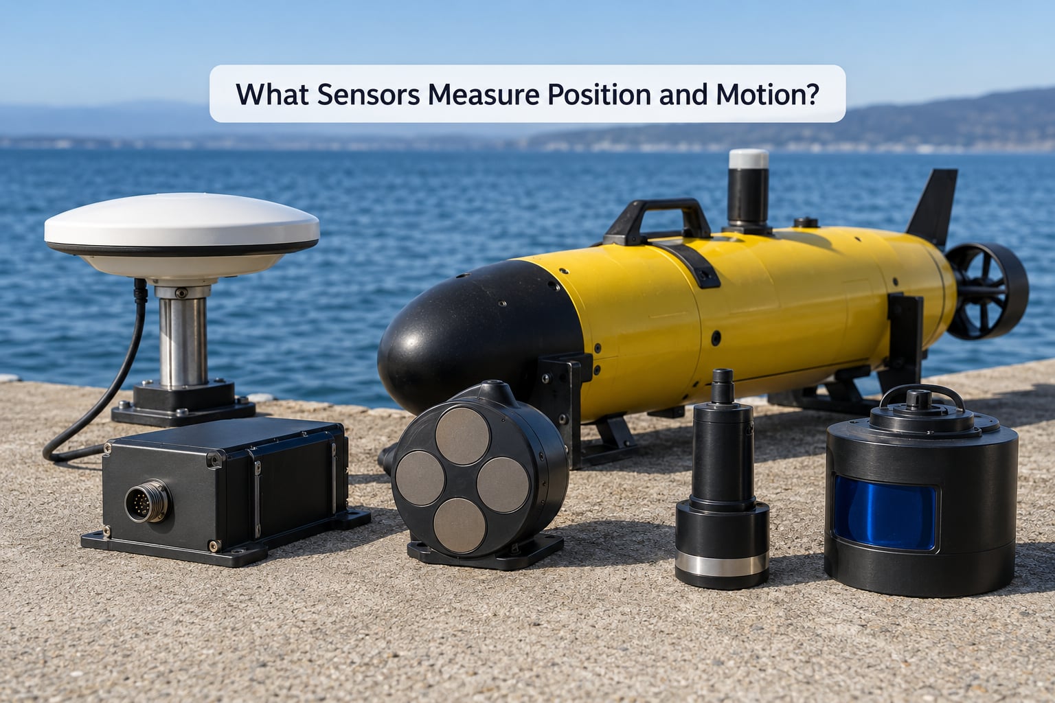
Each sensor contributes a different piece of the puzzle, and each has a specific way of failing. Table providers rank well here because nobody in the top three results uses one.
| Sensor | What it measures | Drift contribution | Typical failure |
|---|---|---|---|
| Inertial measurement unit | Angular rate and specific force | Bias-driven, grows fast | Bias change after vibration or temperature swing |
| Doppler velocity log | Velocity relative to seabed or water mass | Low while bottom-locked | Altitude beyond bottom-track range |
| Pressure depth sensor | Depth below surface | Small, roughly constant offset | Zero drift, slow response in swell |
| Wheel or propeller encoder | Distance travelled along the vehicle axis | Slip-dependent | Slip on soft or sloped seabed |
| Acoustic range (USBL or LBL) | Distance to a known reference | Intermittent correction only | Multipath and poor sound speed profile |
| Surface GPS fix | Absolute position | Resets all accumulated error | Unavailable below the surface |
How a DVL works
A DVL transmits at least four angled acoustic beams and listens for the echo off the seabed. It measures the frequency shift of each return, and that shift is a direct velocity measurement along each beam. Combine four beams and you get velocity in three axes, along with a figure of merit that tells you how good those measurements were.
Because it measures movement relative to the ground rather than the water, a DVL is the single most valuable addition to an underwater dead reckoning stack. It converts an unbounded drift problem into a nearly bounded one.
What a magnetometer cannot do underwater
A magnetometer heading works well near the surface and becomes useless below roughly 20 to 30 metres of conductive seawater. This is why an underwater vehicle needs a gyrocompass or a north-seeking gyro instead. Heading reference underwater is a solved problem; magnetic heading simply is not an option.
How Do Inertial Sensors Estimate Underwater Movement?
An accelerometer measures specific force, not acceleration. Subtract gravity and you have linear acceleration, and integrating acceleration once gives velocity. Integrate velocity a second time and you get displacement. That double integration is the whole game, and it is also where inertial dead reckoning dies.
Because you integrate twice, a constant bias of 0.01 metres per second squared produces about 0.5 metres of position error every second. Double integration of pure accelerometer data is effectively unusable beyond roughly 5 to 20 seconds without an external velocity reference.
Gyroscopes measure angular rate and suffer the same accumulation in orientation, just at a different rate. Two failure modes dominate in practice. Bias is a persistent offset that integrates straight into position. Vibration and shock cause scale factor errors that look like bias but are not, which is why a survey-grade IMU mounted on a thruster frame is worse than a cheap IMU mounted on a quiet frame.
This is the honest reason sensor fusion is not optional. The IMU supplies high-rate attitude and the short-term arc of the trajectory. The DVL supplies the velocity that stops the double integration from running away. The depth sensor pins one axis of the solution to a hard physical constraint.
How Accurate Is Dead Reckoning Underwater?
Accuracy depends almost entirely on how you measure heading, because heading error accumulates along the direction of travel rather than randomly.
The relationship is simply the length of the track times the sine of the heading error. At 1 km, a 0.5 degree heading error gives about 8.7 metres of cross-track error. Double the leg to 2 km and you get 17.5 metres. That is why a compass reading good to one degree sounds adequate and behaves catastrophically over a long transit.
A worked example makes the mechanics concrete. Suppose a vehicle takes a GPS fix at the surface, dives, and runs a straight 2 km leg at 1 metre per second with a constant 0.5 degree heading error and no other faults. At the end of the leg the true position is 2,000 metres along the intended track. The dead reckoning estimate sits 17.5 metres to the side of it. Roughly thirty-five minutes of travel produced that seventeen metres, and none of it was visible in the moment.
Add a DVL with a one percent scale factor and the story changes. Velocity error scales with distance travelled, so a 2 km leg accumulates around 20 metres of along-track error but the cross-track error drops to nearly zero, because the heading is now solid. Different error, same order of magnitude, opposite remedy.
A reasonable drift budget by mission duration looks like this:
| Mission duration | IMU only, MEMS | IMU plus DVL | IMU, DVL and periodic acoustic fix |
|---|---|---|---|
| Under 10 minutes | Usually acceptable | Comfortable | Very tight |
| 1 to 3 hours | Not usable | Hundreds of metres of drift | Metres to tens of metres |
| Multi-day survey | Not usable | Not usable without aiding | Tens of metres if fixes arrive on schedule |
The lesson is that you should report a position together with its confidence. A vehicle that publishes an uncertainty ellipse growing at a known rate is telling the operator something far more useful than one publishing a five decimal place coordinate that is hundreds of metres wrong.
What Happens When the DVL Loses Bottom Lock?
This is the most common real failure in underwater dead reckoning, and it is worth understanding in detail because it is quiet. Nothing alarms. The data just quietly stops being about the ground.
Every DVL has an altitude limit. Above it, the echoes are too weak to process and the unit switches to water track mode, reporting velocity relative to the surrounding water mass instead of the seabed. A vehicle swimming in a steady current now believes it is stationary while it is being carried along at current speed.
Other causes of bottom-lock loss include fish and bubbles returning strong false echoes, mobilised sediment such as sandwaves that scatter the signal before it reaches hard ground, and multipath in stratified water where a sound speed profile bends echoes along unexpected paths.
Good units handle this with figure of merit weighting. Each beam reports its own quality, and the velocity solution is weighted accordingly, so one degraded beam cannot drag the whole solution. Beam rejection goes further and drops bad beams outright. Equal-weight averaging, by contrast, lets a single useless beam poison an otherwise clean measurement, and the accumulated error over a survey leg is dramatic.
The practical rule: if the DVL altitude is above the manufacturer’s bottom-track range, dead reckoning has quietly reverted to its un-aided state. Track that condition explicitly and warn the operator.
How Do You Correct an Underwater Position Estimate?
A correction is any external measurement that pulls the estimate back. The trick is knowing which one you can afford at the moment you need it.
Surface GPS fixes. The cleanest correction available, and it resets everything. It is also the most expensive in time. Every surfacing costs energy, interrupts the mission, and risks detection for military platforms.
Acoustic positioning. A transponder on the seabed emits a known pinger; the vehicle measures range, and with several beacons or an array with known geometry it gets a full position fix. USBL uses a single reference and an array on the vehicle, which suits small ROV work but degrades with range and angle. LBL uses a local seabed array and gives better accuracy in survey areas, at the cost of needing that array deployed first. Both are limited by the sound speed profile: sound bends with temperature and salinity, and if you assume a straight ray you will place yourself wrongly at range.
Terrain and seabed matching. Compare the seafloor profile from a multibeam or echosounder against a stored map and correct the estimate when they align. It needs no infrastructure at all, which is why it is so attractive for AUVs working over unmapped or repeat-surveyed ground.
Visual landmarks. For a diver or a camera-equipped ROV near a known structure, feature matching works but degrades fast with turbidity and range. It is a supplement, not a primary aid.
As a practical order of preference: use whatever absolute aid the mission allows, fall back to terrain matching when no aid exists, and fall back to drift-bounded dead reckoning only as a last resort.
What Is the Difference Between Dead Reckoning and GPS Navigation?
They are not competing methods. GPS supplies absolute position; dead reckoning supplies the continuous motion estimate that fills the gaps between fixes. Real navigation stacks use both, and a surface vessel does exactly the same thing.
There is a useful second distinction here, the one that trips people up. Strictly, dead reckoning uses true course steered and speed through the water only. Add tide, set, drift and leeway and you are computing an estimated position, an EP. Many sources use the two terms interchangeably, and the Admiralty Manual of Navigation and Bowditch do not, which is why the YBW forum still has people quoting chapter and verse at each other.
For an underwater vehicle the practical gap is smaller, because there is no tide table worth consulting at depth. Currents still exist, though, and a vehicle that neglects them is quietly running an EP while believing it is doing DR.
How Can Marine Robots Make Dead Reckoning More Reliable?
Reliability comes from process discipline more than from buying a better sensor. A few habits do most of the work.
Calibrate the alignment, not just the sensor. The most common source of systematic error is a DVL mounted at an angle to the IMU axes that the software believes is zero. Check DVL-to-IMU heading misalignment, velocity scale factor and tilt offset on a calibration run, then validate it on a closed loop where you return to a known mark.
Fuse rather than cascade. A Kalman filter or extended Kalman filter that weights IMU, DVL, depth and acoustic measurements together will beat any sequential scheme, because it can down-weight a sensor the moment that sensor misbehaves.
Estimate biases, do not just compensate for them. A filter that treats accelerometer bias and gyro bias as states to be estimated can actually remove them. A filter that only uses velocity to correct velocity will not.
Model the vehicle. DVL lever-arm offsets between the sensor and the centre of rotation, thruster-induced water flow past the sensors, and current velocity all belong in the model if you care about metres rather than tens of metres.
Synchronise time properly. A DVL, an IMU and an acoustic modem all producing timestamps from different clocks will produce a solution that looks fine and is wrong in a way you cannot see. Hardware time stamping or a disciplined clock shared across sensors is worth the effort.
Log everything and validate before open water. Record raw sensor data, not just fused output, so you can replay a failed run. Test in a pool or a tank where the true path is known before you trust a mission over a seabed you have not surveyed.
Frequently Asked Questions
Can dead reckoning replace GPS underwater?
No. Dead reckoning has no absolute reference, so its error grows with every timestep and never resets on its own. GPS is what anchors it: a vehicle takes a surface fix, integrates motion through the dive, and returns to the surface for another. On short shallow tasks dead reckoning alone can be good enough, but on any mission where you must return to a specific point, an acoustic aid or terrain matching is what keeps the estimate honest.
How fast does inertial dead reckoning drift?
It depends entirely on sensor grade and duration. Accelerometer-only double integration is effectively unusable after roughly 5 to 20 seconds. A MEMS IMU without velocity aiding loses useful accuracy within minutes. Add a DVL and a 2 km transit holds to within tens of metres rather than hundreds. The honest way to answer the question for your own vehicle is to log raw sensor data and replay it, not to trust a spec sheet.
Do underwater vehicles need a compass?
Yes, but not a magnetic one. Below roughly 20 to 30 metres of seawater the Earth’s magnetic field is too distorted for a magnetometer to give a usable heading, so vehicles rely on a gyrocompass, a north-seeking gyro or a ring laser gyro. Heading accuracy still matters enormously: 0.5 degrees of heading error produces about 8.7 metres of cross-track error over a 1 km leg, and nearly 17.5 metres over 2 km.
What is the best sensor for underwater navigation?
For most vehicles the answer is a Doppler velocity log, because it measures velocity relative to the seabed and therefore removes the double integration problem that ruins inertial-only dead reckoning. A quality IMU is a close second and is required regardless, since the DVL measures velocity but not orientation. Depth from a pressure sensor is cheap and worth including. Acoustic positioning is not a sensor on the vehicle so much as an external aid.
How often should an underwater robot receive a position fix?
Often enough that the uncertainty growth stays inside your task tolerance. A survey that must stay within 5 metres needs fixes more frequently than one tolerating 50 metres. For a small ROV, acoustic fixes every few minutes are routine. For a multi-day AUV survey, the usual answer is to design the mission so the vehicle must pass close to an acoustic beacon at planned intervals rather than surfacing at all.
Does dead reckoning work without a GPS signal?
That is the entire point of it. Once you have a starting position, dead reckoning needs no external signal at all, which is why it is the only navigation method that always has an answer underwater. The cost is that the answer gets less trustworthy the longer you go without a real fix, so treat it as a bounded estimate with a growing confidence radius rather than a position you can bet a vehicle on.
Getting Started With Underwater Dead Reckoning
Start with one honest measurement rather than a pile of hardware. Fly a straight known line at a constant speed with a decent IMU, log the raw data, and see how far off you are at the far end. That number tells you which of the three fixes you actually need.
For most builders the sequence is a decent IMU first, then a DVL, then an acoustic aid for the missions that need metres rather than tens of metres. How dead reckoning works underwater stops being an abstraction the moment you have seen your own error curve grow.