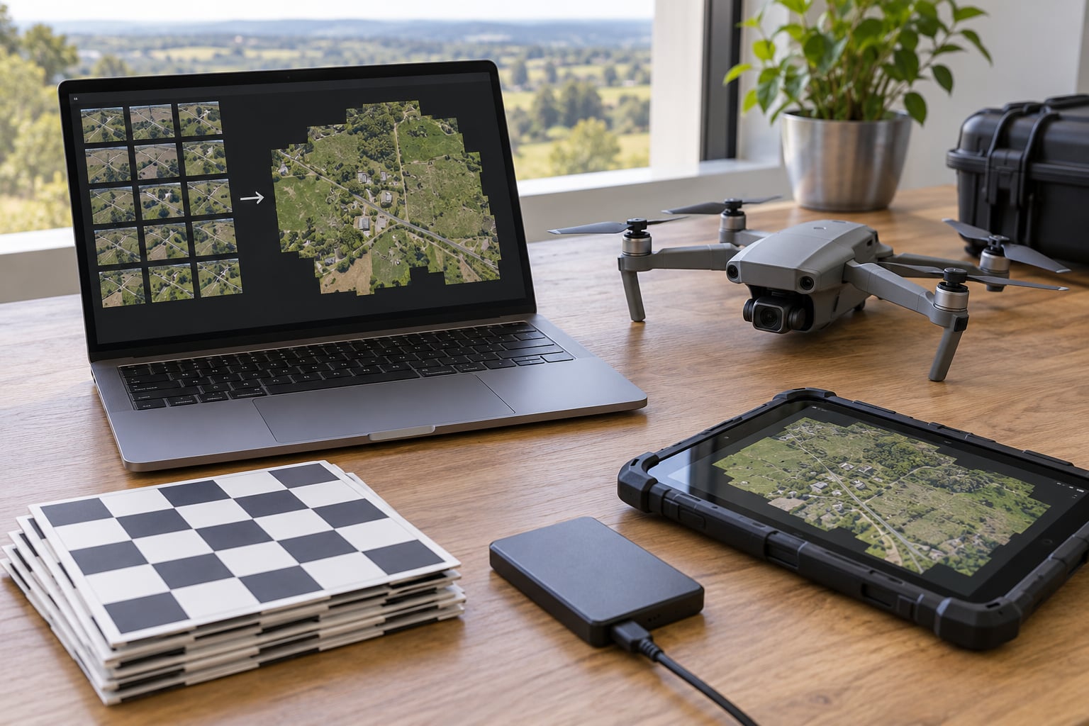
To stitch drone photos into a map, you run structure-from-motion photogrammetry over a set of heavily overlapping aerial images and project them onto a reconstructed 3D surface, producing a single georeferenced orthomosaic where every pixel carries a real-world coordinate. Most of the accuracy is decided before takeoff, in your overlap, altitude and control points, not in the software. A small site of a few hundred images will process in an evening on a decent laptop.
The short version, in six steps:
- Decide the output: orthomosaic, point cloud or surface model, plus the ground resolution and coordinate reference system you need.
- Calibrate the camera and place ground control points, or fly an RTK/PPK aircraft and log checkpoints separately.
- Fly a grid with consistent altitude and generous overlap, then take a second pass if the surface is vegetated, wet or repetitive.
- Import the images with EXIF and GPS metadata intact, and sort out blurred frames before processing.
- Align the photos, read the sparse point cloud, then build the dense cloud and the surface model.
- Export the orthomosaic as a GeoTIFF in the right coordinate reference system, then measure the error against your checkpoints.
Skip a step and the map still comes out. It just comes out wrong in ways that are hard to see, which is the problem this guide is aimed at.
Table of Contents
- What You Need
- Step-by-Step: How to Stitch Drone Photos Into a Map
- Common Mistakes
- Frequently Asked Questions
- What is the best software for stitching drone photos into a map?
- How much overlap do drone photos need for photogrammetry?
- Do I need GPS coordinates to make a map from drone photos?
- How accurate should a drone map be for field research?
- Can I stitch non-overlapping hand-held photos into a map?
- What file format should I export for use in GIS software?
- Conclusion
What You Need
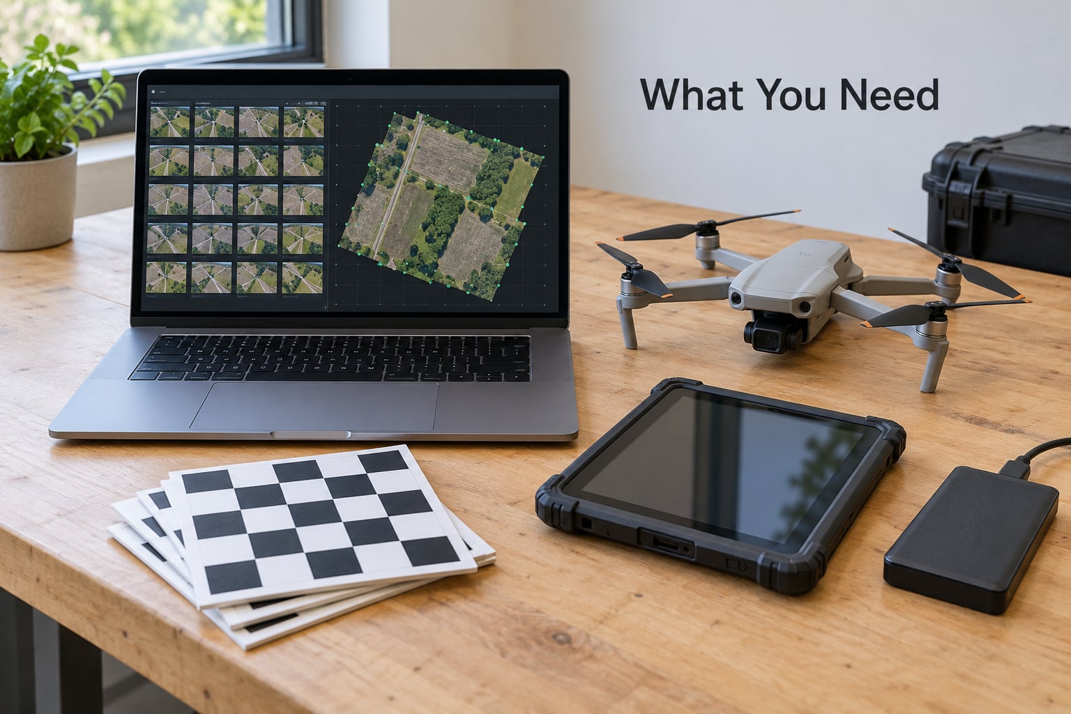
A stitching workflow has five inputs, and only one of them is the drone. Get the other four right and you can work with a fairly ordinary aircraft.
A camera that shoots in manual mode. Any camera with a fixed, known lens will do. What matters is that the shutter speed, ISO, aperture and white balance stay identical across the flight, because the software relies on the same features looking the same in every frame. Phone cameras can work for small, textured sites, but their rolling shutter and automatic processing make results inconsistent at the edges.
GPS-tagged imagery from a stable flight plan. Every frame should carry its own position in the EXIF data, which lets the processor scale the reconstruction even before you add ground control. A grid flight with constant altitude is what turns a pile of pictures into a measurable surface.
Mapping software that runs structure from motion. The free and open-source route is real and capable: OpenDroneMap is the engine, WebODM is the browser front end most people install, and Node-ODM is the command-line version for a server or a Raspberry Pi. The commercial tools are DJI Terra, Pix4D, Agisoft Metashape and DroneDeploy, with Esri reality mapping folded into ArcGIS Pro. All of them follow the same six-step pipeline; the differences are how much tuning they expose, how fast they run, and what they charge.
| Option | Type | Good fit | Watch out for |
|---|---|---|---|
| WebODM / OpenDroneMap | Free, open source | Small to medium sites, teams already comfortable with command lines | You supply the computer, and dense clouds on a laptop will exhaust the RAM |
| DJI Terra | Commercial, free tier | Projects flown on DJI aircraft with RTK | Works best inside the DJI ecosystem |
| Pix4D | Commercial | Survey and inspection work with checkpoint validation | Processing time scales quickly with image count |
| Agisoft Metashape | Commercial, per seat | Power users who want control over every stage | The manual workflow is steeper than the guided ones |
| DroneDeploy | Commercial, cloud | Teams that want a finished map without running anything locally | Your imagery leaves your machine |
A computer with real headroom and somewhere to put the files. A 200-image job is unremarkable. A 4,000-image job over forest or a shoreline can ask for 32 GB of RAM before the dense cloud is finished, and the intermediate files run to several times the size of your raw images. Budget 10 GB per thousand images on fast storage, and keep scratch space separate from your project drive.
Ground control and a known output format. Control points are the difference between a picture that looks right and a map you can measure. Know before you fly whether the deliverable is a GeoTIFF, a point cloud in LAS or LAZ, a surface model, or just a PDF for a site meeting.
Step-by-Step: How to Stitch Drone Photos Into a Map
1. Define the Output and Survey Area
Start by deciding what the map has to do, because that sets everything else. Measuring stockpiles and earthworks needs a surface model as well as an orthomosaic. Crop monitoring needs colour consistency. Site progress tracking needs repeat flights from the same altitude, on the same day type, so the images compare.
Work out your ground sampling distance next. GSD is the size of one pixel on the ground, and it is set by altitude and camera rather than by software. A 20 MP camera on a 1 inch sensor at 60 m gives roughly 2.5 cm per pixel, which is plenty for shoreline change and vegetation plots; drop to 40 m when you need to see the edge of a small beach wrack line.
Set the coordinate reference system in advance and write it in your field notes. For field research on a local site, a state plane or national grid metric system is usually right. EPSG:4326 is fine for web display and rough measurements, but it will distort area and distance, which matters the moment anyone computes a change in volume.
Plan the boundary with a buffer. A common re-fly cause is a tidy grid that stops exactly at the site edge, where only a couple of images overlap and the reconstruction has nothing to hold onto. Fly 20 to 30 percent beyond the boundary in every direction, and work out the overlap you need for the surface before you set the flight altitude.
| Surface | Front overlap | Side overlap | Altitude note |
|---|---|---|---|
| Flat built site, gravel, hard standing | 75% | 65% | Standard baseline; fly conservatively if the site is small |
| Uniform crops, short grass, sand | 80% | 80% | Repeating rows ghost badly, so add a cross pass |
| Dense forest, scrub, tall vegetation | 85% | 85% | Drop to around 60 m and slow down; expect a weak surface model |
| Shoreline or mudflat with water | 80% | 80% | Add a second flight at a different time if the water level is changing |
| Corridor, river, road | 80% | 70% | Fly the centreline twice, offset, to kill seam artefacts |
| Vertical structures, towers, façades | 85% | 85% | Add oblique passes; low side overlap makes towers lean outward |
That 75/65 baseline is where most tutorials start. In practice, moving to 85 percent forward and side overlap gives noticeably cleaner orthophotos, and flying lower and slower beats cranking the overlap slider when the software cannot find features in vegetated ground. Treat the table as a starting point and raise the numbers when the result disappoints.
2. Calibrate the Camera and Prepare Ground Control
Camera calibration is the lens and sensor geometry: focal length, principal point and the distortion coefficients that make a wide lens bend straight lines. Modern software can solve calibration from the images themselves, which is why checkered calibration boards matter less than they used to. If you do have a board, take 20 to 30 photos of it from different angles and distances before the flight and let the software use them.
It is the ground control that actually anchors a map. Mark at least five to seven points spread across the whole site, each one a distinct, high-contrast target visible from the air: a painted cross, a survey marker, a sheet of checkerboard. Survey them with a GNSS receiver if you can, and write down the coordinates before you leave the site, not from memory later.
Separate your control points from your checkpoints. Control points constrain the solution, so they are no longer a fair test of it. Hold back at least three or four measured points that the software never sees, and measure the finished map against those. That single habit is what turns a pretty picture into a defensible survey.
If your aircraft has RTK, you get accurate per-image positions and may need only a handful of checkpoints. PPK does the same job after landing by logging the base station data on board. Neither replaces checkpoints, and neither rescues a flight with bad overlap or inconsistent altitude.
3. Capture a Consistent Overlapping Flight
Set the drone to manual exposure and lock it: one shutter speed, one ISO, one aperture, one white balance, fixed focus. Auto exposure will shift brightness between frames, and the mosaic blending step will then fight you to make bright and dark areas match. Overcast or hazy-bright conditions suit this well; harsh midday sun on wet sand or water produces glare and blown highlights that no blending mode can repair.
Hold altitude steady and keep the shutter fast enough to freeze motion, usually 1/500 s or faster at mapping altitude. Leave the lens alone, never digital zoom, and shoot in the format the software supports natively. Avoid filters, and if you must shoot in a compressed format, use the least compression available.
Give yourself a second pass wherever the surface repeats. Roofs, gravel, crops, boardwalks and water all produce ghosting along the seams because the software matches the wrong feature. A flight 20 to 30 m higher than the first, offset by half a line, breaks up those patterns quickly. Overlap points into a grid rather than crossing them, and check the aircraft logs and a few images on the tablet before you land.
Morning and evening light is easier on the software, not because of the drama but because shadows are long and soft rather than short and hard. A tall object that casts a hard shadow at midday is a hole in the point cloud that no amount of overlap will fill.
4. Import and Organize the Images
Copy the raw files straight off the card and work on the copy. Then import them into your photogrammetry software with the structure from motion engine selected, and choose the option that keeps EXIF data, including the GPS tags. This is the single most common beginner mistake: exporting images out of a phone app or a photo editor strips the coordinates, and the software then has no idea how large the site is or where it sits.
Keep the original filenames. They usually encode the camera and the capture order, which makes it far easier to find a specific frame when something in the middle of the block came out blurred.
Do a fast triage before processing. Open a contact sheet and drop out the frames that are blurred, badly underexposed, or taken during a turn. Removing 5 to 10 percent of a marginal set often saves an hour of processing, and those images rarely contribute useful tie points anyway. Organise the rest into subfolders by flight line or sortie if you flew more than one pass, since that makes selective re-processing possible later.
5. Run the Stitching and Alignment Process
Stitching is feature matching in disguise. The software looks for distinctive patches, such as the corner of a container or a knot in a boardwalk, in one photo and then hunts for the same patch in its neighbours. Strong matches become tie points, and the bundle adjustment solves for the position and orientation of every camera at once, producing the sparse point cloud.
Look at that sparse cloud before going further. Its job is to tell you whether the flight worked. Points should spread evenly across the whole site, not bunch in the middle. Long trails of stray points over water or shadow mean matches went wrong, and clusters of noise at the edges mean your buffer was too small. Low reprojection error, usually a fraction of a pixel, is a good sign; a value several pixels high means the calibration or the overlap is wrong and densifying now is wasted effort.
Upload or enter your control points here and re-run the optimisation, then check the residuals at each point. A control point with a large residual is telling you something specific, usually a mistyped coordinate or a target the software matched to the wrong thing.
Build the dense point cloud next, then the surface. On a typical job, a key point limit around 40,000 and a tie point limit around 4,000 with medium dense quality is a sensible starting point; a height field mesh suits terrain that is roughly a single surface, while a more complex mesh is needed for structures and overhanging geometry. If the software offers depth filtering, use it near water, glass and shadow, which otherwise fill the cloud with garbage points.
6. Review and Export the Map
Inspect the orthomosaic before you export it, and inspect it with a ruler rather than a scroll wheel. Zoom in on the control points and confirm the target centres land where they should; zoom out and look for the failure patterns, seams, wobbling edges, doubled features and soft patches where blending smoothed over a hole.
Check scale against something of known size, a vehicle, a marked path, the target dimensions, and check geographic placement by overlaying the mosaic on a basemap. Then export as GeoTIFF with LZW compression in the coordinate reference system you chose in step 1, and export the quality report alongside it. That report holds the reprojection error, the checkpoint residuals, the ground sampling distance and the point cloud density, and it is the evidence that the map holds up in a review.
For anything larger than a site, build a pyramid with overviews so it opens quickly, and keep the 3D model and surface model rather than just the picture. A change-detection project in six months will need both.
If the source photos are gone and all you have is a warped or shifted stitched image, you can still recover a usable map by georeferencing in QGIS: place control points on the image, run the georeferencer with a thin plate spline transformation, then merge and reproject with gdalwarp to EPSG:4326 with LZW compression. Expect to spend a good while placing at least ten points spread across the frame, and more like thirty for a clean result. It works, but reprocessing the raw imagery is usually the better use of an afternoon.
Common Mistakes
Almost every bad map traces back to one of a handful of causes, and they are all visible in the pattern of the failure.
| What you see | Likely cause | Fix | Field tip |
|---|---|---|---|
| Gaps and holes in the mosaic | Not enough overlap, or exposure too dark for the software to find features | Re-fly at 85/85, or raise the light and re-shoot | Fly 20 to 30 percent past the site boundary so the edges have support |
| Map is bent or wavy | Low-texture surfaces, water, dense canopy, wrong camera calibration | Add control points, re-run alignment, filter the dense cloud | Drop to around 60 m and slow the flight over vegetation |
| Towers and poles lean outward | Side overlap too low, no oblique passes | Add cross and oblique passes at 85 percent side overlap | Photogrammetry cannot see a wall that no image actually faced |
| Ghosting along seams, doubled edges | Repeating textures, crossing flight lines, varying exposure | Offset the second pass, lock exposure, switch to mosaic blending | Rough gravel and crop rows are the usual culprits |
| Map is shifted or the wrong size | Wrong coordinate reference system, or GNSS without correction | Reproject to the correct CRS, or survey control points and restart | Write the EPSG code in your field notes before takeoff |
| Edges fall apart in a perfect grid flight | Flight stops at the boundary, so few images see the edge | Re-fly with a buffer, or restrict the area of interest inward | This is the most common reason for an unnecessary second flight |
| Blurry frame ruins a block of the map | Slow shutter or a turn during capture | Remove the frame and re-process, or re-shoot that line | Check images on the tablet before you land, not after |
Two habits prevent most of that list. Fly a consistent grid, and check the result against held-back checkpoints before you build anything on top of it.
Frequently Asked Questions
What is the best software for stitching drone photos into a map?
For a small site with no budget, WebODM running on OpenDroneMap is genuinely capable and free. DJI Terra suits DJI aircraft with RTK, Pix4D and Agisoft Metashape suit professional survey and inspection work, and DroneDeploy handles everything in the cloud. All of them run the same structure-from-motion pipeline, so the deciding factors are the computer you have, how much tuning you want, and where your imagery is allowed to sit.
How much overlap do drone photos need for photogrammetry?
The usual baseline is 75 percent forward overlap and 65 percent side overlap, which covers flat built sites. Increase to 80/80 for uniform crops, sand and shorelines, and to 85/85 for dense forest, water and vertical structures. Many operators push everything to 85 percent or fly lower and slower instead, because consistent altitude and good texture fix more problems than overlap numbers alone.
Do I need GPS coordinates to make a map from drone photos?
You need position data of some kind, because without it the software can build a shape but not a coordinate system, and distances and areas come out wrong. Every frame should keep its EXIF GPS tags, and you either fly an RTK or PPK aircraft or survey ground control points yourself. Hold back several measured points as checkpoints so you can measure the real error after processing.
How accurate should a drone map be for field research?
Accuracy is set by control, overlap and the scale of the feature you are measuring, not by the software. Hold out checkpoints and report the real figure rather than the best residual. For change detection, aim for error well below the change you are trying to measure, which usually means a second flight from the same altitude under comparable light.
Can I stitch non-overlapping hand-held photos into a map?
Not usefully. Structure from motion needs overlapping views of the same features, so a set of photos with little or no overlap will fail to align or produce a distorted, unmeasurable result. Photographs taken from the ground can still be processed, but they need roughly 60 to 80 percent overlap, plenty of textured subjects in view, and even then the result is a panorama rather than a top-down orthomosaic.
What file format should I export for use in GIS software?
GeoTIFF is the safe default: it carries the coordinate reference system inside the file, keeps full pixel detail, and opens directly in QGIS and ArcGIS without a sidecar file. Add LZW compression so the file stays workable, and build pyramid overviews for anything large. Use a projected CRS rather than EPSG:4326 if you will measure area or distance in the field.
Conclusion
Stitching drone photos into a map is six decisions in a fixed order: define the output and resolution, calibrate and place control, fly a consistent overlapping grid with a buffer past the boundary, import with metadata intact, align and check the sparse cloud before densifying, then export a GeoTIFF in the correct coordinate reference system and measure the error against held-back checkpoints.
Before you process your first flight, sort out the overlap for the surface you are mapping, the calibration, and where the control points will go. Everything that goes wrong afterwards traces back to one of those three.