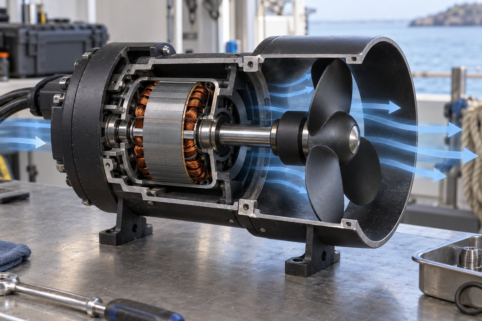
An ROV thruster is a sealed electric motor driving a propeller inside a duct, and it moves the vehicle by pushing water backward. That is the whole mechanism. Everything else about a thruster — the housing, the shaft seal, the motor controller, the position of the unit on the frame — exists to make that push quiet, controllable and reliable at depth.
Getting how ROV thrusters work matters at three different levels. If you are specifying equipment for a work-class vehicle, the numbers decide whether it can hold station in a two-knot surface current. If you are buying two thrusters for an inspection class, the question is usually thrust per watt and depth rating. If you are building something at home on a weekend, the same physics explains why the thruster you bought performs worse than the datasheet promised.
Updated for October 2026.
Table of Contents
- What Does an ROV Thruster Do?
- How ROV Thrusters Work From Motor to Water Flow
- Propeller, Impeller and Other ROV Thruster Types
- Thruster Specifications That Actually Matter
- How Thrust Changes with Speed and Water Conditions
- Brushless vs. Brushed Thruster Motors
- How ROV Thrusters Are Controlled and Positioned
- Choosing Thrusters for an ROV
- Testing and Maintaining Thrusters Safely
- Frequently Asked Questions
- What is an underwater thruster?
- What is the difference between static thrust and free-flow thrust for an ROV?
- How much thrust does an ROV need, and how is it calculated?
- Can an ROV thruster be reversed to move backward?
- Why does an ROV thruster perform worse near the seabed?
- How should I test a new ROV thruster safely?
- Conclusion
What Does an ROV Thruster Do?
A thruster’s job is to produce a force on the vehicle, in a direction you choose, at a magnitude you control. That is all. It converts electrical energy stored in batteries (or pulled down the tether) into momentum in seawater, and the difference between those two things is what accelerates the vehicle.
It is worth being clear about what a thruster is not. A pump moves water without producing a useful net force on a vehicle, because it discharges in every direction or into a plumbed return. A propeller with no motor behind it is a turbine, useful only in a current. Control surfaces — fins, rudders, dive planes — need forward flow across them to generate a side force, so at zero speed they do nothing at all. An ROV spends most of its working life at zero speed, hovering inches from a hull, which rules control surfaces out almost entirely.
What a Thruster Is Not
Thrusters also differ from a boat’s outboard in one way that catches people out: an ROV has no mass to trade against. A surface craft gets forward motion partly by pushing a large mass of air aside cheaply. Underwater, water is roughly 800 times denser than air, so every litre accelerated backward costs about 800 times the force for the same acceleration. That is why an ROV that weighs 45 kilograms in water needs tens of newtons of continuous thrust just to move at walking pace, and why a thruster that looks small on a datasheet is the correct size.
Commercial ROV thrusters for inspection and light work-class vehicles sit in a familiar band: roughly 7 to 25 kgf of static thrust, 360 to 1315 W of continuous power, and depth ratings from about 30 m up to 350 m. Those three numbers alone tell you most of what you need for a first cut at sizing.
How ROV Thrusters Work From Motor to Water Flow
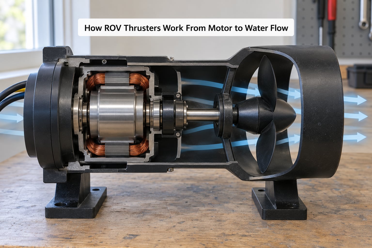
The energy path is short and every link in it loses something. Reading a thruster datasheet as a chain of five steps makes the losses obvious.
- The tether or battery pack supplies DC power. A work-class ROV is powered from the surface, which means the energy cost per newton is almost irrelevant. An AUV carrying its own batteries has the opposite problem.
- The ESC, or motor controller, switches that power to the motor phases. It decides direction of rotation and how fast the shaft turns, and it protects the motor from over-current and overheating.
- The brushless DC motor converts electrical energy into shaft rotation. The rotor turns, the shaft turns with it, and the winding gets warm doing it.
- The propeller on that shaft accelerates water backward. A duct or shroud around it keeps the flow from spilling sideways and recovers some of the swirl energy.
- The reaction pushes the vehicle forward. Newton’s third law: the water gains backward momentum, so the vehicle gains equal forward momentum.
The last step is the one people get wrong. The thruster is not “sucking” the vehicle along, and the duct is not a jet engine. The force is a reaction. If the propeller pushes a mass of water backward with force F, an equal and opposite force F acts on the propeller hub, and through the shaft, the motor and the frame, on the vehicle. This is why a thruster bolted rigidly to a frame produces a very large reaction load at the mounting flange — a 25 kgf thruster pulls forward with about 245 newtons on four bolts, in tension, in water, all day.
Reversing the motor reverses the rotation, which reverses the thrust. That is how an ROV goes astern without a gearbox, and it is also why a thruster that has to run astern a lot carries a bidirectional-rated motor and controller rather than a cheap single-direction one.
Propeller, Impeller and Other ROV Thruster Types
Almost all ROV thrusters use an open three- or four-blade propeller, and the interesting differences are in what surrounds it and where it points.
Open Propeller
A bare propeller bolted to a motor. It is light, it has few surfaces to foul or snag, and it gives the best thrust per watt at forward speed. Its two problems are damage and safety: an exposed three-blade spinner is a genuine hazard to anyone working near the vehicle, and it will take trawl gear, rope and cable without complaint.
Ducted Thruster
The propeller sits inside a short cylinder, called a duct, shroud, nozzle or Kort nozzle depending on who is describing it. The duct does three useful things: it limits the radius at which divers and tether can reach the blades, it recovers some of the energy in the swirling water, and it raises static thrust noticeably for a small fat-bladed propeller. The catch is at speed: the duct adds skin friction drag, so a ducted unit falls behind an open propeller on long transits. For a vehicle that spends its life hovering on station, that trade is usually worth taking.
Tunnel Thruster
A ducted unit set into an external tunnel through the hull, so its flow is drawn from clean water outside the vehicle rather than from the disturbed flow around the frame. A pair mounted as bow thrusters gives sideways authority at zero speed. The disadvantages are real: a tunnel in the hull is a pressure boundary that can leak, the two openings add drag during forward transit, and a bow thruster that is far forward creates a turning moment the rear thrusters have to work against, so the vehicle yaws when you use it.
Vectored Thruster
A thruster on a pivoting mount that can swing its thrust vector, usually 20 to 40 degrees, controlled by a servo or a geared stepper. Six vectored thrusters — four horizontal, two vertical — can hold position, orient the camera and hold depth in current with fewer control problems than a fixed layout. The cost is mechanical: every pivot is a sealing surface, a servo is another motor that can fail, and the control authority comes at the price of more failure modes. Hobby builders do this successfully; on a work-class vehicle the redundancy argument usually wins instead.
| Attribute | Open propeller | Ducted thruster |
|---|---|---|
| Static thrust for a given frame size | Lower | Higher, often 20 to 30 percent |
| Thrust per watt in forward transit | Better | Worse, duct drag at speed |
| Debris and rope strike risk | High | Low, blades shielded |
| Fouling and cleaning | Simple, blades exposed | More surfaces, gaps to trap weed |
| Cavitation limit | Lower tip speed for the same thrust | Higher, duct suppresses tip vortices |
| Typical ROV use | AUVs, USVs, transiting vehicles | Inspection and work-class ROVs, DPVs |
Blade Count and Pitch
Three blades is the ROV default: a good compromise between smoothness, strength and cost. Two blades are cheaper and typically more efficient on a high-speed vehicle, but they spin faster for the same thrust and load up more unevenly. Four and five blades appear in low-speed, high-thrust units where large blade area matters more than smoothness.
Pitch is the other lever. Low pitch means broad, blunt blades that bite hard at zero speed and produce high static thrust, but slide inefficiently once forward. High pitch does the opposite: quiet and efficient in transit, weak at station keeping. Most ROV thrusters are deliberately low pitch, because holding position against current is the job.
Thruster Specifications That Actually Matter
Most thruster datasheets are a wall of numbers with no order of importance. Here is the order that matters when you are choosing.
| Specification | What it means | Why you care |
|---|---|---|
| Static (mooring) thrust | Force produced at zero forward speed, usually in kgf | The single most useful number for an ROV. 1 kgf is 9.81 newtons |
| Continuous power | Watts drawn at full thrust held indefinitely | Sets your power budget and tether conductor gauge |
| Thrust-to-power ratio | kgf per watt or newtons per watt | The efficiency number that matters at zero speed |
| Diameter and blade count | Propeller size and how many blades | Larger and slower means more static thrust from the same power |
| RPM / KV | Unloaded speed per volt | Too high and the propeller cavitates; too low and it stalls |
| Voltage | Battery or tether voltage at the terminals | Must match your power system, including voltage drop down the tether |
| Depth rating | Maximum working pressure, often 30 m to 350 m | Check the whole assembly, not just the housing |
| Duty rating | Continuous or short-duration capability | A 30-minute thruster will cook in a mission that hovers for two hours |
| Mass | Thruster weight in air | Matters a lot on a small frame that has to be neutrally buoyant |
| Term | Meaning in plain English |
|---|---|
| Static thrust | Thrust with the vehicle held still. Also called mooring thrust |
| KV rating | Roughly RPM per volt with no load. A 300 KV motor on 24 V free-runs near 7200 RPM |
| Advance ratio | Forward speed divided by propeller tip speed. Low means working at a standstill |
| Added mass | The extra inertia a body picks up because it is dragging seawater with it |
| Cavitation | Vapour bubbles forming on the blades when local pressure falls below the vapour pressure of water |
| 6-DOF | Six degrees of freedom: surge, sway, heave, roll, pitch, yaw |
How Thrust Changes with Speed and Water Conditions
Static thrust versus free-flow thrust
Static thrust is measured with the vehicle restrained, usually in a test stand or a tank. Free-flow thrust is measured while the thruster is actually moving water past itself at speed. Free-flow is always lower for the same power input, sometimes dramatically so: a ducted thruster might make 12 kgf static and noticeably less when free-running at survey speed. Neither number is wrong, and a datasheet that gives you only one of them is telling you the flattering half.
There is a second, less obvious effect in the other direction. A high-pitch propeller run at low forward speed can draw more power at half speed than at full speed, because the blade is stalled rather than working. Builders see a thruster that sags, heats up and sounds strained at the exact moment they try to creep along a hull, and the cause is usually pitch, not a failing motor.
How ROV Thrusters Perform in Current and Near the Seabed
Current is the condition an ROV actually works in. A thruster that is pointed across a steady current sees a much higher inflow than the one next to it pointed with it, and the vehicle yaws toward the weaker thruster unless the pilot corrects. Worse, near the seabed a thruster ingests sand and shell grit, and that grit acts like a grinder on bearings, seals and the propeller’s leading edges. Suspended sediment does the same thing more slowly.
Near the surface, the opposite problem appears. A propeller breaking the surface entrains air, thrust collapses, and the resulting noise and vibration shake the vehicle. Thrusters are routinely mounted a little below the top of the frame precisely to keep them submerged in a mild swell.
Cavitation deserves its own mention. As tip speed rises, the pressure on the blade’s suction side drops. Below the water’s vapour pressure, the water boils locally into bubbles that collapse on the next downstream surface, and the propeller suddenly produces less thrust, gets hot and starts eroding. This is the hard ceiling on RPM. You cannot simply take a propeller designed for air and spin it faster in water — water carries the load, and the water itself starts to break down first.
Brushless vs. Brushed Thruster Motors
Nearly every purpose-built ROV thruster uses a brushless DC motor, and the reason is heat. A brushed motor wastes a meaningful share of its input power as friction and heat at the commutator, in a sealed housing underwater, where the only way out is through the housing wall into the surrounding water.
| Attribute | Brushed DC | Brushless DC |
|---|---|---|
| Commutator wear | Consumes brushes, generates debris in the housing | None, position sensors instead |
| Efficiency | Lower, losses at the brushes | Higher, losses mostly in copper and iron |
| Controller | Simple, can run directly off the battery | Needs a matched ESC with good low-speed commutation |
| Reversing direction | Trivial | Requires the ESC to support reverse |
| Electromagnetic noise | Brush arcing is a continuous noise source | Switching noise from the ESC, needs good filtering |
| Typical use | Small homebuilt vehicles, budget builds | Everything commercial, from inspection to work class |
The ESC is part of the thruster, not an accessory to it. Commutation quality at low RPM decides whether the vehicle can crawl at 0.1 m/s or only surges. A thruster with a good motor and a cheap controller will be loud, jerky and hot, and no amount of propeller trimming will fix it. That combination of failure is why experienced builders buy the controller as carefully as the motor.
Heat is also why thruster housings are water-cooled by default. The surrounding seawater is the heat sink, which is why a thruster can sustain full thrust for hours at depth and why it can cook a vehicle in a warm, shallow, poorly ventilated pool.
How ROV Thrusters Are Controlled and Positioned
Thrusters come in horizontal and vertical sets, and the geometry of the frame determines which motion each pair can produce.
| Motion | Axis | How a four-horizontal, two-vertical layout produces it |
|---|---|---|
| Surge | Forward and back | All four horizontal thrusters together, forward or reversed |
| Sway | Sideways | Diagonal pairs, two for each direction |
| Heave | Up and down | The two vertical thrusters, on opposite sides of the centre of buoyancy |
| Yaw | Rotation about the vertical axis | Differential thrust: boost the diagonal on one side, cut the other |
| Roll and pitch | Rotation about the longitudinal and transverse axes | Differential vertical thrust, or vectoring the horizontal thrusters |
That table is the answer to the most-asked question on ROV forums, which is why ROVs need so many thrusters. Four is the practical minimum for useful inspection work: forward, back, sideways, rotate, up and down. Six is the common answer, and six is where differential control gets good enough that a pilot can hold station over a weld seam while a current pushes the vehicle sideways.
Turning the pair of vertical thrusters into roll and pitch control only works if the vehicle is close to neutrally buoyant. If the buoyancy is set well off neutral, the buoyancy moment dominates and the thrusters are fighting a much larger force than the tilt they are trying to correct. Neutral buoyancy is not a cosmetic target; it is what makes the control feel predictable.
What thrust allocation means
Thrust allocation is the job the control system does between your joystick and the six ESCs. You command “strafe to port at half power”. The controller has to decide, for every thruster, what signed power level produces that motion, given the thrusters’ positions relative to the vehicle’s centre of mass and centre of buoyancy. The mathematics is a small matrix of geometry that you solve each cycle, usually tens of times a second, using measured thrust rather than the nominal datasheet value.
Measured thrust matters because real thrusters are not symmetric. Cheap units differ from each other by a noticeable margin, and a vehicle with a mismatched pair will drift constantly even at neutral command. Pilots call this a vehicle that spins instead of moving forward, and it is nearly always unbalanced mounting angles or an uncalibrated pair, not a control bug.
Open-loop control means the controller assumes each thruster produces the power it was told to. Closed-loop control means a depth sensor, heading compass or altimeter closes the loop: the controller measures the result and corrects. Below about a metre of altitude, closed-loop depth holding is close to mandatory, because open-loop depth drifts as the vehicle’s buoyancy changes with temperature and as silt reduces the lift it gets from the water. Any decent ROV has a depth sensor feeding the controller, and that sensor is doing more for vehicle quality than an expensive thruster upgrade.
Fail-safe behaviour is the part worth designing deliberately. Signal loss, ESC failure and power brownout should each have a defined outcome, and the usual choice is motors stop rather than motors run at the last command received. A thruster that keeps spinning at full power when a control link drops is a hazard to the vehicle, the tether and anyone in the water.
Choosing Thrusters for an ROV
Work through these in order. Skipping to step one is how people end up with a vehicle that cannot hold depth.
- Mass and buoyancy. Get the vehicle neutrally buoyant in service conditions, not in a tank on the bench.
- Drag and target speed. Estimate drag from a coefficient times frontal area times velocity squared, then add the drag of the current the vehicle will work in.
- Per-axis thrust. Divide the requirement across the thrusters on that axis and add a margin, typically 30 to 50 percent for thrusters that must also hold station in current.
- Thrust per thruster. Convert to kgf and pick the next standard size up.
- Power budget. Multiply the count by continuous power, add 30 percent for controller losses, then size the tether conductors, breakers and connectors.
- Depth rating and frame space. Check the depth rating against the working depth with margin, and confirm the mounting flange fits your frame.
Worked sizing example
Take a 45 kg inspection vehicle with a plate-like frontal area of 0.5 square metres and a drag coefficient around 0.9, targeting 1.5 knots, which is 0.77 m/s. In seawater at 1025 kg/m³, that gives roughly 137 newtons of drag, or about 14 kgf. Add a 40 percent margin and you need around 20 kgf of total surge thrust, so two thrusters of 10 to 12 kgf each is the sensible starting point.
Now add current. In a 0.3 m/s current, the water and the vehicle see a relative velocity near 1.07 m/s, and since drag rises with the square of velocity the requirement jumps to roughly 265 newtons, about 27 kgf. That is the number that decides whether the vehicle can hold station or gets dragged downcurrent, and it is routinely the number builders forget. A two-thruster pair picked at 12 kgf each will not hold in that current; a four-thruster arrangement at the same rating will.
Power follows from the same arithmetic. Four horizontal thrusters in the 10 to 12 kgf class and two vertical units of similar size draw something in the order of 3 to 4 kW at full output. At 48 V through the tether that is 60 to 85 amps, which is a surface power supply and cable design decision, not a thruster decision. Work out the power and the current margin before you pick anything, then choose the thruster that fits inside the number you have.
Testing and Maintaining Thrusters Safely
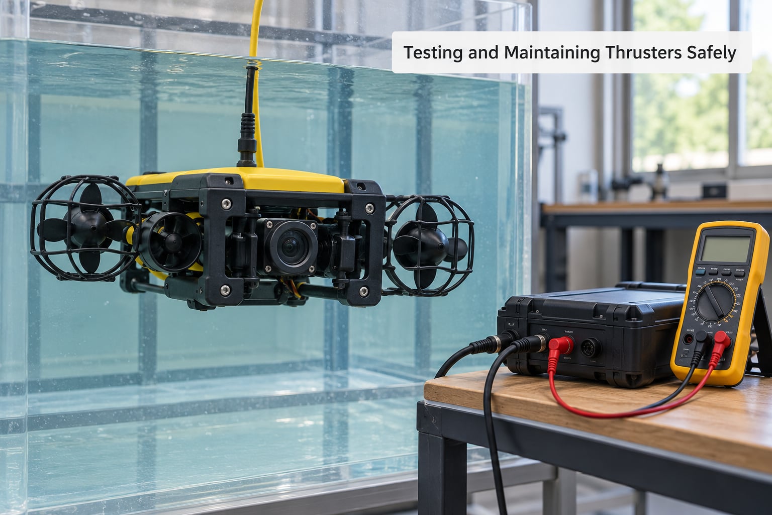
A thruster is a rotating blade in water with a battery attached. Test it in that order of risk, and never skip the electrical steps because they are boring.
- Isolate before you open anything. Disconnect the battery or the surface supply, confirm with a meter that the terminals are dead, and lock out the supply while the housing is open.
- Check for damage dry. Look at the propeller for bent blades and chipped leading edges, the cable entry for a displaced seal, and the shaft for play that suggests a bearing or a failed seal.
- Guard the propeller before the first spin. On the bench, fit a guard or duct. Anyone near a spinning propeller should be behind it, not beside it.
- Free-run it in air briefly, then in a tank. Air gives you a clean noise and spin check at low risk. A tank test shows the real static thrust, the current draw and the behaviour under water.
- Measure, do not assume. Record the current at full command, check the case temperature after several minutes at full thrust, and compare against the datasheet. A thruster drawing noticeably more than rated is a warning, not a personality.
- Leak-check the assembly before it goes in the water. Submerge the connected, powered-down unit and look for bubbles at the shaft seal and cable entry.
New thrusters are often quiet, then loud, then hot as they settle. A healthy unit develops a smooth low hum with a little gear-like whine from the commutation, gets warm rather than hot, and stops when commanded. Unhealthy signs are grinding or rattling that scales with command, a sharp change in note at a particular throttle position, or a smell of scorched insulation on a brushless unit that has been under-thrust and stalled.
What fails in service, in rough order of frequency, is worth knowing before it happens. Seals wear and start weeping oil or admitting water, and most small homebuilt failures start at the cable entry rather than the propeller shaft. Bearings and shafts corrode once a seal lets water in, and the corrosion is what kills the bearing. Propellers foul with weed, line and netting, and a fouled thruster pulls hard against its own tether. Motor controllers fail from heat, water ingress or a supply voltage spike, and a dead controller usually means a dead thruster with no way to reverse it.
Two habits remove most of that. Keep a spare propeller and a spare thruster on the deck, which is why counter-rotating spares are so widely recommended. And inspect the propeller and cable entries at every deployment, which takes two minutes and catches fouling before it becomes a mission abort.
Frequently Asked Questions
What is an underwater thruster?
An underwater thruster is a sealed electric motor driving a propeller inside a duct or shroud. It pushes water backward and moves forward by reaction force, so it produces thrust even at zero speed. Purpose-built ROV units are usually brushless DC, rated in kgf of static thrust, and sealed for depths from roughly 30 m to 350 m.
What is the difference between static thrust and free-flow thrust for an ROV?
Static thrust is the force produced with the vehicle held still, and it is what an ROV needs most, because hovering on station is the normal working condition. Free-flow thrust is measured while the thruster is already moving water past itself, and it is always lower for the same power. A datasheet that quotes only one of the two is showing you the flattering number.
How much thrust does an ROV need, and how is it calculated?
Estimate drag as half the water density times a drag coefficient times frontal area times velocity squared, then add the current velocity and apply a 30 to 50 percent margin. Divide across the thrusters on that axis. Holding station in a 0.3 m/s current can require roughly double the thrust needed for the same speed in still water.
Can an ROV thruster be reversed to move backward?
Yes. Reversing the motor reverses the rotation of the propeller and therefore the thrust, which is how an ROV goes astern without a gearbox. It needs a controller that supports reverse, and it works best at low differential thrust, since full reverse on several thrusters at once produces a lot of turbulence and noise.
Why does an ROV thruster perform worse near the seabed?
Near the seabed a thruster ingests sand, shell grit and suspended silt. That grit abrades bearings, shaft seals and the leading edges of the propeller, and a fouled propeller loses efficiency and pulls hard against the tether. A thruster that is slower or noisier near the bottom is usually not electrical, it is mechanical wear.
How should I test a new ROV thruster safely?
Isolate and confirm dead with a meter before opening anything, inspect the propeller, shaft and cable entry, and fit a guard before the first spin. Run it briefly in air, then in a tank, measuring current draw and case temperature against the datasheet. Never handle a thruster while it is powered, and never work on it with the tether connected to a live surface supply.
Conclusion
How ROV thrusters work comes down to a short chain: the ESC drives a brushless motor, the motor turns a propeller, the propeller accelerates water backward, and the reaction moves the vehicle. Everything else — ducted versus open, blade pitch, thruster count and placement, closed-loop depth hold, sealing and depth rating — is about getting the most usable thrust out of that chain in water that is dense, moving and full of sand.
Start where the physics starts. Work out the total thrust your vehicle needs per axis in the current it will actually work in, add your margin, and turn that into a power number and a tether current. Then choose thrusters that fit inside those two numbers, and test each one on a stand or in a tank before you trust a datasheet figure.