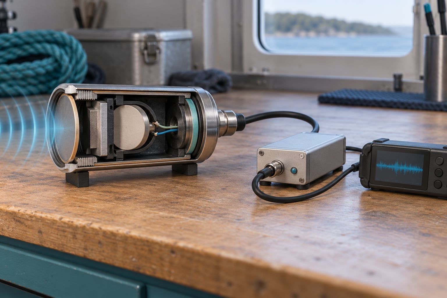
A hydrophone is an underwater microphone: it senses pressure changes travelling through water and converts them into an electrical signal you can amplify, filter and record. Most use a piezoelectric element that flexes with the wave and produces a small voltage. It listens only, and it never transmits.
If you work on boats, ocean drones or habitat monitoring, this explains why the sensor is the easy part and the electronics behind it are the hard part. Understanding the chain tells you where your data quality comes from, and where it quietly disappears.
Table of Contents
- What Is a Hydrophone and What Does It Do?
- How Hydrophones Work: From Water Pressure to an Audio Signal
- What Are the Main Hydrophone Technologies?
- What Is the Signal Chain After the Sensor?
- Which Frequency Response Do You Need?
- How Do You Choose a Hydrophone for Marine Research?
- How Are Hydrophones Used on Sailing Robots and Ocean Drones?
- What Are the Main Limitations and Sources of Error?
- Frequently Asked Questions
- Conclusion: What to Do First
What Is a Hydrophone and What Does It Do?
A hydrophone converts acoustic energy in water into electrical energy for listening. It detects things a microphone in air would miss: whale calls, snapping shrimp, the low groan of a passing ship, the click of a piling being driven.
Hydrophone: a passive underwater receiver. Pressure in, voltage out, no transmission.
Two things separate it from other underwater gear. First, it is receive-only. A sonar transducer does both jobs, sending out a ping and receiving the echo. Second, it is built for water rather than air, which changes almost every part of its design.
| Device | Transmits? | Receives? | Typical use |
|---|---|---|---|
| Microphone | No | Yes, in air | Recording, PA, studio |
| Hydrophone | No | Yes, in water | Marine bioacoustics, ocean noise monitoring |
| Sonar transducer | Yes | Yes | Depth sounding, echo sounding |
| Sonobuoy | Varies | Yes | Surface-deployed listening station |
How sound moves through water
Sound is mechanical: a pressure wave, not an electromagnetic one, so it needs matter to travel through. In seawater it moves at roughly 1,500 metres per second, about four times faster than in air.
Water is also far denser. That gives sound a very different impedance, the product of density and wave speed, and impedance is what decides how much energy crosses into a sensor. Almost all of the energy in an underwater sound is reflected away from an air-based microphone. A hydrophone’s diaphragm and housing are shaped to receive it instead.
Why we can’t hear well underwater
Your ear is matched to air. The outer and middle ear work as an air-filled impedance transformer, and their moving parts are sized for air densities. Drop that assembly into water and almost no acoustic energy reaches the eardrum, so everything sounds faint and dull.
Two workarounds exist. Divers hear bone conduction through the skull, which bypasses the air path. And a helmet-mounted air pocket keeps a bubble of air against the ear, which is why that helmet trick works at all.
How Hydrophones Work: From Water Pressure to an Audio Signal
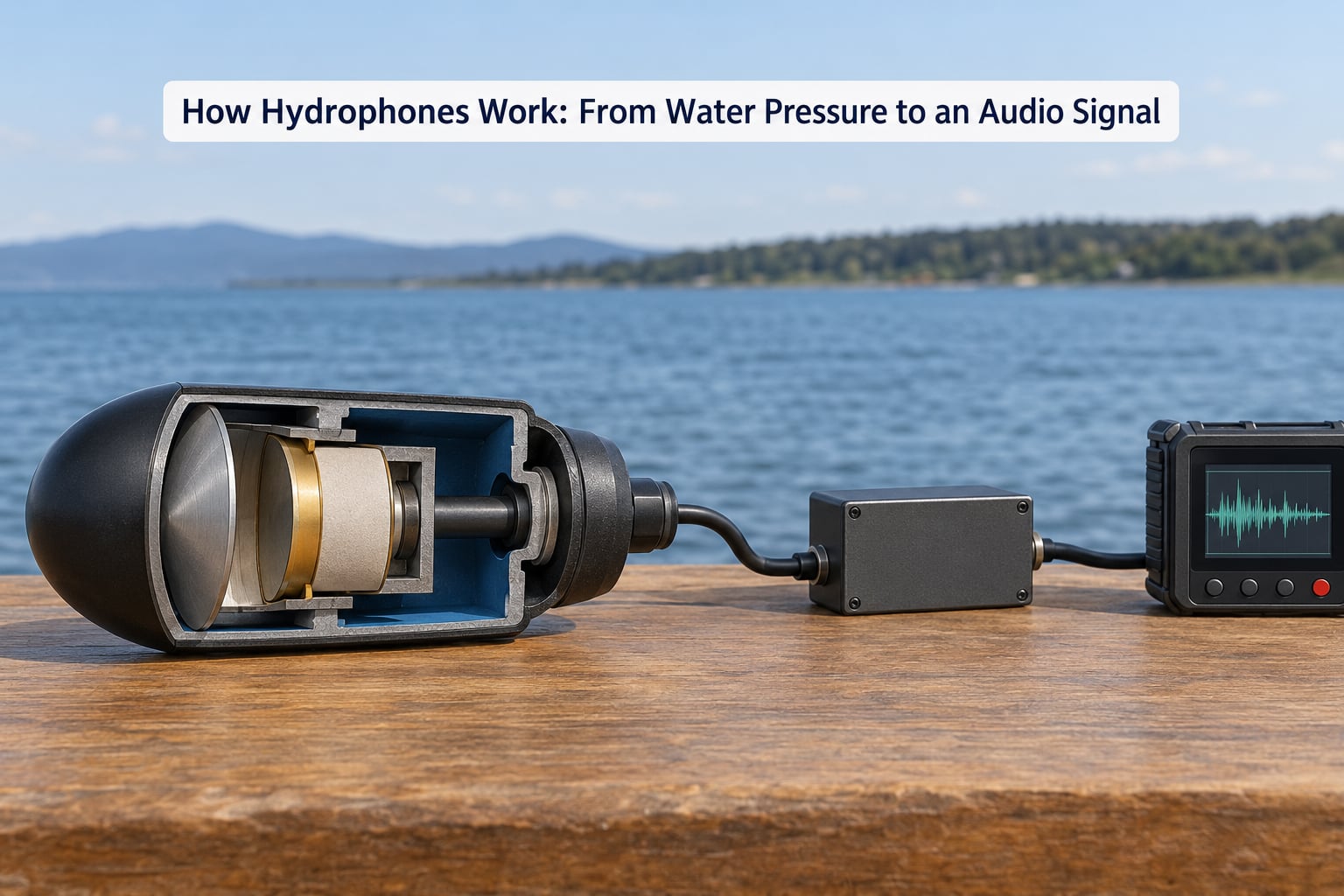
The whole mechanism is a five-step chain, and every step after the first one is electronics rather than acoustics.
- Pressure reaches the element. A diaphragm on the front of the sensor flexes inward and outward as the wave passes.
- The element deforms. The diaphragm is bonded to a piezoelectric ceramic disc or plate, so the pressure bends it slightly.
- Charge appears. Flexing a piezoelectric material pushes charges on its two faces, and the separation of charge is an alternating voltage.
- The signal is conditioned. A pre-amplifier raises the microvolt-level output, and filters remove unwanted energy.
- The signal is digitised and stored. An analog-to-digital converter samples the waveform, timestamps it and writes it to a recorder or sends it up a cable.
Piezoelectricity is the property that makes step three work. Squeeze a piezoelectric crystal or ceramic and it develops a voltage across its faces. Reverse the squeeze and the polarity flips. No power supply is needed, because the material generates its own signal from the sound pressing on it.
Ceramics such as lead zirconate titanate give the strongest output but are delicate. Quartz and tourmaline are tougher and quieter, which is why they turn up in long-duration moored deployments. Either way, the sensing element needs a fluid coupling layer so pressure in water transfers efficiently to the disc rather than bouncing off.
Directivity comes from the housing, not the element
The element itself is nearly omni-directional: it responds equally to pressure arriving from any side. What shapes the pattern is the housing.
- Omni-directional housings have no reflector, so a level in every direction is a level in all directions. Most research sensors are omni.
- Hemi-directional housings add a baffle that shadows the rear hemisphere, improving signal-to-noise ratio for a known source direction.
- Directional or DIHYDRA-style units combine a pressure-sensing element with a pressure-gradient element to form a cardioid pattern, which helps reject ambient noise.
What Are the Main Hydrophone Technologies?
All of them share the same job. The differences are in the sensing element, the noise floor, the power needs and how far the signal has to travel before it turns into a number.
| Technology | Sensing element | Typical sensitivity | Strengths | Limitations |
|---|---|---|---|---|
| Piezoelectric ceramic | PZT disc under load | 20 to 200 uV/Pa | Wide bandwidth, no power needed, cheap | Fragile, high source impedance, drifts with temperature |
| Piezoelectric quartz | Quartz/tourmaline bar | About 1 uV/Pa | Very stable, low self-noise | Low output, needs an excellent pre-amp |
| Electret | Capacitive membrane plus JFET | High | Low noise, cheap, easy DIY builds | Moisture sensitive, limited depth without potting |
| MEMS | Microscopic capacitor diaphragm | Moderate | Low noise, stable, very low power | Lower sensitivity, needs case pressure compensation |
| Fiber optic | Interferometric light path | High | Immune to electrical noise, multiplexes easily | Needs a light source and interrogation unit, expensive |
| Active integrated | Element plus on-cable electronics | Fixed gain output | No separate pre-amp, long cable runs, low power | Less flexible gain control |
For a first build, ceramic wins on bandwidth and cost. For a year-long mooring with an 80 dB dynamic range target, quartz or MEMS is a better answer.
What Is the Signal Chain After the Sensor?
A hydrophone element produces something on the order of a microvolt per pascal. That is a very small signal, and everything after it exists to lift the signal above the noise around it.
Cable and pre-amplifier
Cabled sensors send their raw output up to shore, and uncabled ones amplify inside a pressure housing on a battery. Either way, a pre-amplifier sits in the path, and its own noise sets the floor for what you can record.
Ceramic sensors are capacitive sources, often around 19 kOhm and 8 nF at 1 kHz, so the amplifier has to drive a reactive load rather than a resistor. Low-noise JFET input op-amps are the usual answer because they present a very high input impedance. Protection diodes at the input are cheap insurance, because a dropping sensor or a switching spike can destroy the front end.
Filtering, digitisation and storage
The hard part for beginners is noise budgeting. Take a common ceramic sensor at 40 uV/Pa and a quiet deep-water ambient of roughly 10 uPa at 1 kHz. The signal from ambient noise at that level is about 0.4 uV. An amplifier with 5 nV per root-Hz of voltage noise sits around a 125 uPa equivalent level, which means you would be recording your amplifier, not the ocean.
One field rule of thumb is to get pre-amplifier voltage noise below roughly 0.4 nV per root-Hz so you stay ambient-noise limited instead of pre-amp limited. That needs a genuinely low-noise part.
Bit depth is the second half of the problem. Ambient ocean noise falls off at roughly 17 dB per decade, so the recording is dominated by very low frequencies. A 10-bit converter offers about 60 dB of range, and you spend most of it on the sea rumble while the sound you want near 1 kHz vanishes below the quantization floor.
The practical fix is either a 24-bit converter, which gives roughly 108 to 120 dB, or a high-pass filter with a corner around 10 to 30 Hz. On a simple build the filter is just a matter of dropping the input coupling capacitors from tens of microfarads down to roughly 1 nF to 1 uF. Filtering costs you low frequencies and saves your whole record.
Sampling rate matters too. It has to cover your highest frequency of interest, and for arrays the channels must be sampled on the same clock. Sampling channels one after another introduces a skew that destroys time-difference-of-arrival estimates.
Time stamping closes the chain. Every file needs a reliable clock, ideally disciplined by GPS or a PPS signal, so that recordings from multiple units can be compared later.
Which Frequency Response Do You Need?
Start from the sound, not the sensor. A broadband response is convenient for general recording, but most marine projects care about one band.
| Band | What lives there | What it suits | Watch out for |
|---|---|---|---|
| Low frequency, roughly 10 to 200 Hz | Ship machinery, wind waves, ice, some large whale calls | Vessel noise studies, long-range monitoring, AUV self-noise checks | Flow noise, mooring strum, 1/f ambient noise |
| Broadband, roughly 10 Hz to 20 kHz | Most natural and mechanical sound | Soundscape recording, general monitoring, film sound | Needs a wide, flat element and good pre-amp |
| High frequency, roughly 20 kHz and up | Snapping shrimp, sonar pings, echolocation clicks | Inshore reef work, bat-like dolphin clicks, sonar detection | Cable capacitance and aliasing limit the usable ceiling |
Frequency response also sets array geometry. At 1 kHz, half a wavelength in seawater is about 75 cm, so that is roughly the maximum spacing between elements. Content well above the frequency the array was spaced for will alias spatially and produce phantom directions, which is why array work usually targets 100 to 1000 Hz.
How Do You Choose a Hydrophone for Marine Research?
Work down this list in order. It is the same order that decides whether a deployment succeeds or produces a season of unusable data.
- Sensitivity tells you the output per unit pressure. Ceramic sensors usually run from about 20 to 200 uV/Pa; higher sensitivity means a healthier signal into the pre-amp.
- Self-noise is the sensor’s own noise floor, quoted as a spectral level in dB re 1 uPa/Hz. It has to sit below the ambient noise you intend to record, or you are listening to the sensor.
- Dynamic range spans the quietest sound you care about and the loudest you must survive without clipping. This is usually a ADC and pre-amp decision as much as a sensor one.
- Frequency range should cover your target band with margin, and the response should be flat there. A curve that sags 10 dB across your band makes equal amplitude mean two different things.
- Depth rating is a hard limit, not a guideline. Check the housing and connector, not just the element.
- Corrosion and biofouling decide how long a deployment lasts. Titanium housings and sacrificial anodes buy time in salt water.
- Connector type matters more than it sounds. Waterproof connectors rated for depth are expensive because getting the seal right is genuinely hard.
- Power comes from shore for cabled units and from batteries for uncabled ones. Uncabled deployments are usually the limiting factor on mission length.
- Calibration records let you correct for the gain drift that happens between deployments.
- Field replaceability decides whether a cable fault ends a season or costs one day.
Units worth knowing before you read a datasheet
Sensitivity appears as uV/Pa or as dB re 1 uPa. Self-noise appears as a spectral level in dB re 1 uPa per Hz. Mixing those up is the single most common source of confusion in hydrophone data: a band level in dB re 1 uPa and a spectral level in dB re 1 uPa/Hz are different quantities, and comparing them directly makes a sensor look far worse than it is.
How Are Hydrophones Used on Sailing Robots and Ocean Drones?
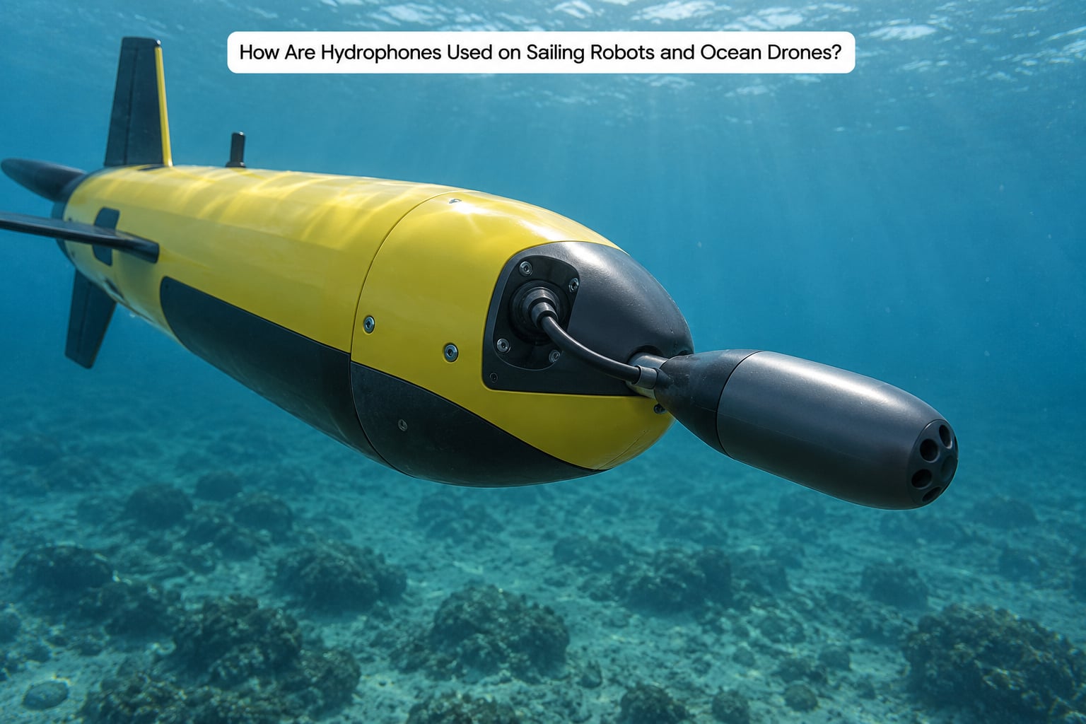
On an autonomous craft the hydrophone is a payload, not a standalone instrument, and the integration decisions dominate everything else.
Mount it where the flow is laminar. Boundary-layer turbulence at the hull is loudest right where a sensor usually wants to sit. Placing the element in a faired fairing or inside a leading-edge standoff moves it into cleaner water and can cut self-noise by 10 to 20 dB.
Isolate it mechanically. Engine, thruster and payload vibration couple straight into the housing. A compliant mount between the element and the frame keeps that energy from becoming electrical signal in the piezo itself.
Protect it on impact. Sailing drones surfacing hard in a swell are the usual way these sensors die. A recessed mount or an impact cage buys back the rest of the mission.
Record coherently. If you want direction, every channel needs the same clock and simultaneous sampling. With three or more elements spaced about half a wavelength apart at your target frequency, you can steer a beam and separate overlapping sources.
Let the vehicle react to what it hears. Onboard processing rules out the long cable to shore, so the drone has to decide locally: detect a propeller signature and slow down, spot an odontocete click and change depth, count repeated piling noise and log a position.
Plan the recovery. Every unattended deployment ends with a float, a light, a transponder and a line that floats cleanly. Data is worthless if the sensor is still down there.
What Are the Main Limitations and Sources of Error?
Most disappointing hydrophone recordings are not sensor failures. They are noise that arrived by another route.
- Flow noise. Turbulence across the diaphragm produces pressure that looks exactly like sound. Fix it with a fairing, a slower-moving platform, or a high-pass filter.
- Bubbles. Gas bubbles resonate and collapse against the housing, creating a rushing or clicking layer across the whole band. A drop of antifouling on the housing often settles it.
- Hull vibration. Structure-borne energy entering the housing is converted by the same piezo element. Mount on a compliant isolator, not a rigid bulkhead.
- Mooring strum. A line singing under current tension puts energy straight into the sensor. Add a clump weight above the unit and slack in the mooring.
- Electrical hum and interference. Mains pickup, PWM from thrusters and switching converters all ride in on the same cable as the signal. Shielded cable, a single ground point and filtering at the ADC help more than people expect.
- Cable motion noise. A cable tugging on a connector produces microphonic noise that no filter removes reliably. Strain-relieve at both ends.
- Aliasing. Anything above half the sample rate folds back into the band as false tone. Filter before you digitise, not after.
- Biofouling and pressure effects. Growth on the diaphragm shifts sensitivity, and pressure changes compress a sealed cavity. Both show up as slow gain drift, which is why calibration records matter.
- Temperature drift. Ceramic sensitivities move with temperature. For a season-long mooring this can be several dB without any visible fault.
None of this makes hydrophones impractical. It makes the difference between an instrument that measures the ocean and one that measures its own housing.
Frequently Asked Questions
Is a hydrophone the same as a microphone?
A microphone is built for sound in air; a hydrophone is built for sound in water. The difference is mechanical, not electronic. Water is roughly 800 times denser than air, so almost all the acoustic energy reflects off a microphone diaphragm. A hydrophone uses a fluid-coupled diaphragm and housing tuned to the impedance of seawater, which lets it collect what an air microphone cannot. Both output an electrical voltage.
Can a hydrophone record sounds above the human hearing range?
Yes. Many hydrophones cover 10 Hz to 20 kHz or more, so they capture dolphin echolocation clicks, snapping shrimp and sonar pings that sit above human hearing. Broadband ceramic elements handle this range well, though cable capacitance usually limits the usable ceiling in practice. Record the top of the band only if you have a converter sampling at least twice the highest frequency you care about, plus an anti-alias filter.
Why do hydrophones make bubbles or rushing noises underwater?
A few common causes. Air trapped in the housing and escaping through a seal makes a bubbling, crackling layer across the band. Turbulent flow across the diaphragm adds rushing noise that is pressure, not signal, and looks identical to sound. A mooring line under tension strums and feeds vibration into the sensor. Anti-fouling on the housing, a fairing over the element and slack in the mooring fix most of it.
Do I need a preamplifier for a hydrophone?
Almost always. A ceramic element produces roughly 20 to 200 microvolts per pascal, so without amplification the signal sits below the noise floor of any recorder. Choose a low-noise JFET input op-amp, because the sensor is a capacitive source around 19 kOhm and 8 nF and needs a very high input impedance. Add protection diodes at the input, and aim for voltage noise below about 0.4 nV per root-Hz so the recording stays ambient-noise limited.
How deep can a hydrophone be used?
It depends on the model, not on the principle. School and hobby hydrophones are usually rated to tens of metres, while commercial research units are commonly rated to several hundred metres and some full-ocean-depth units go past 6,000 metres. Check the pressure housing and connector rating, not just the element, and remember that every housing joint is a potential leak point. Fouling and corrosion usually end a deployment before the depth limit does.
Can hydrophones be connected to an Arduino or Raspberry Pi?
You can, but a 10-bit converter such as the MCP3008 gives only about 60 dB of dynamic range, and ambient ocean noise falls at roughly 17 dB per decade, so most of that range gets spent on low-frequency sea rumble. Add a high-pass filter with a corner around 10 to 30 Hz, or use a 24-bit ADC for roughly 108 dB. For multiple channels doing direction finding, sample them simultaneously on one clock.
Conclusion: What to Do First
The core of how hydrophones work is simple: a pressure wave flexes a piezoelectric element, the element produces a voltage, and electronics turn that voltage into data. Everything else on the site, from flow noise to bit depth, is about protecting the signal between those two points.
So define your target sound first, pick the frequency band that contains it, then choose a depth-rated sensor whose self-noise sits below the ambient level where you are deploying. After that, spend your effort on the pre-amplifier, the high-pass corner and a converter with enough range, because that is where most hydrophone projects succeed or quietly fail.
Last reviewed in 2026.